23
Calibration
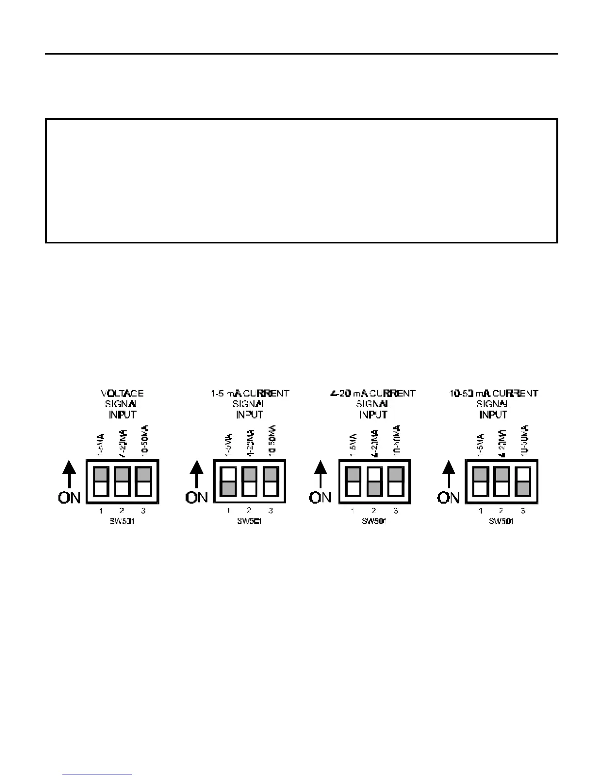
Each DIP switch selects the range for input current following.
DIP switch 1 is for 1 – 5 mA input, DIP switch 2 is for
4 – 20 mA input, and DIP switch 3 is for 10 – 50 mA input.
Warning
Only one DIP switch should be ON at a time and only when
the PCM4 is set up to follow a current signal. All three DIP
switches must be OFF when following a voltage signal.
m
Figure 13. DIP Switch Settings
DIP switches