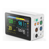
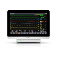
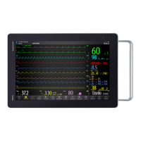
2-2 BeneVision N17/BeneVision N15/BeneVision N12 Patient Monitor Service Manual
Main control board
LCD
iView assembly
(N17 Optional)
DVI
RJ45
2*USB
2*USB
Power switch
board
Alarm lamp
board
MPAN module
(Optional)
TP control
board
AC/DC
module
Battery interface
board
(N15/N17)
Recorder
(Optional)
Speaker
Battery
Front
shell
Back
shell
AC/DC
interface
2*USB 2*USB DVI RJ45
WiFi module
(Optional)
Independent display board
(N17 Optional)
DVI
Internal module com board(4slots/6slots)
4/6*Module
communication
interface
Nurse call
interface
SMR
interface
Bottom
shell
Battery interface
board
(N12/N12C)
Battery
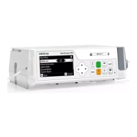
Figure 2-1 System block diagram of the N17/N15/N12/N12C
2.2.1 Main Control Board
There are the main control CPU, program memory, data memory, system configuration memory, system
FPGA, WiFi module (optional), power management MCU, battery charging circuit, and DC-DC circuit on
the main control board. The internal interface and external interfaces are also provided on the board. The
internal interface is an interface between the recorder, internal module rack COM board, AC-DC, and the
battery. The external interfaces refer to the DVI display interface, USB interface, and Ethernet interface.
Main Processor
DDR3
Program
Memory
Data Memory
E2ROM
USB hub
Touch-
controller
SPI
USB
Audio
codec/AMP
Speaker
Touch panel
Power M0
PHY
WiFi
(optional)
Internal Module
Rack communication
board
RTC
Photo
senseor
Power key board
RJ-45
DVI
interface
USB 4*port
MMC
MMC
RMII1
PHY
Independent
display
board/iView
MPAN Module
E2ROM(funnct
ion cfg)
Nursecall
interface
Alarm light
controller
SMR
Interface
FPGA
(N15/N17)
LCD
Back light
driver
DVI
transfer
SPI
UART
LCDC
I2C
I2C
Main
Control
board
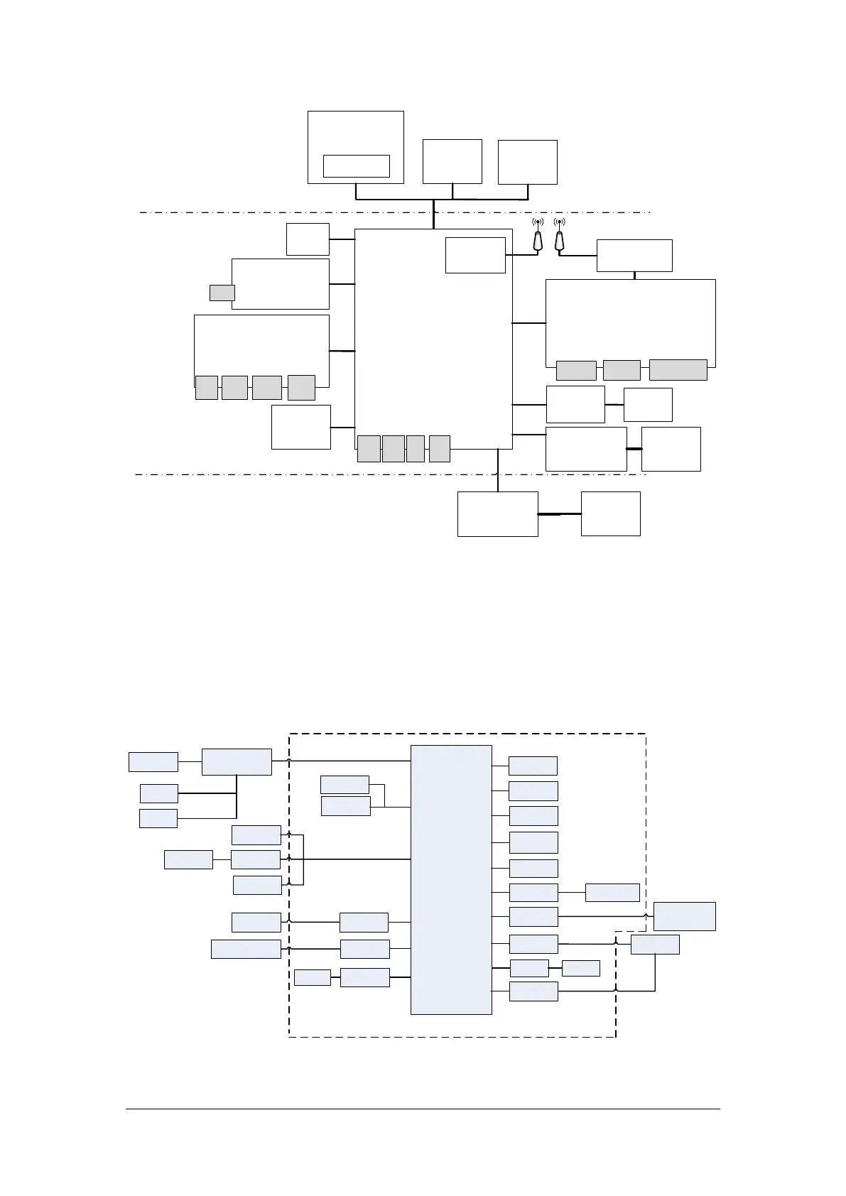
Figure 2-2 Diagram of the main control board