EasyManuals Logo

Mindray BeneVision N12 Service Manual

Mindray BeneVision N12
123 pages
To Next Page IconTo Next Page
To Previous Page IconTo Previous Page
Page #85 background imageLoading...
Page #85 background image
BeneVision N17/BeneVision N15/BeneVision N12 Patient Monitor Service Manual 6-27
4. Removing the internal module rack COMM board.
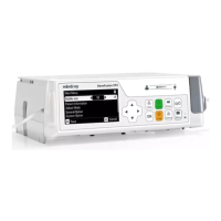
Disconnect the cable between the module rack antenna and the internal module rack COMM board.
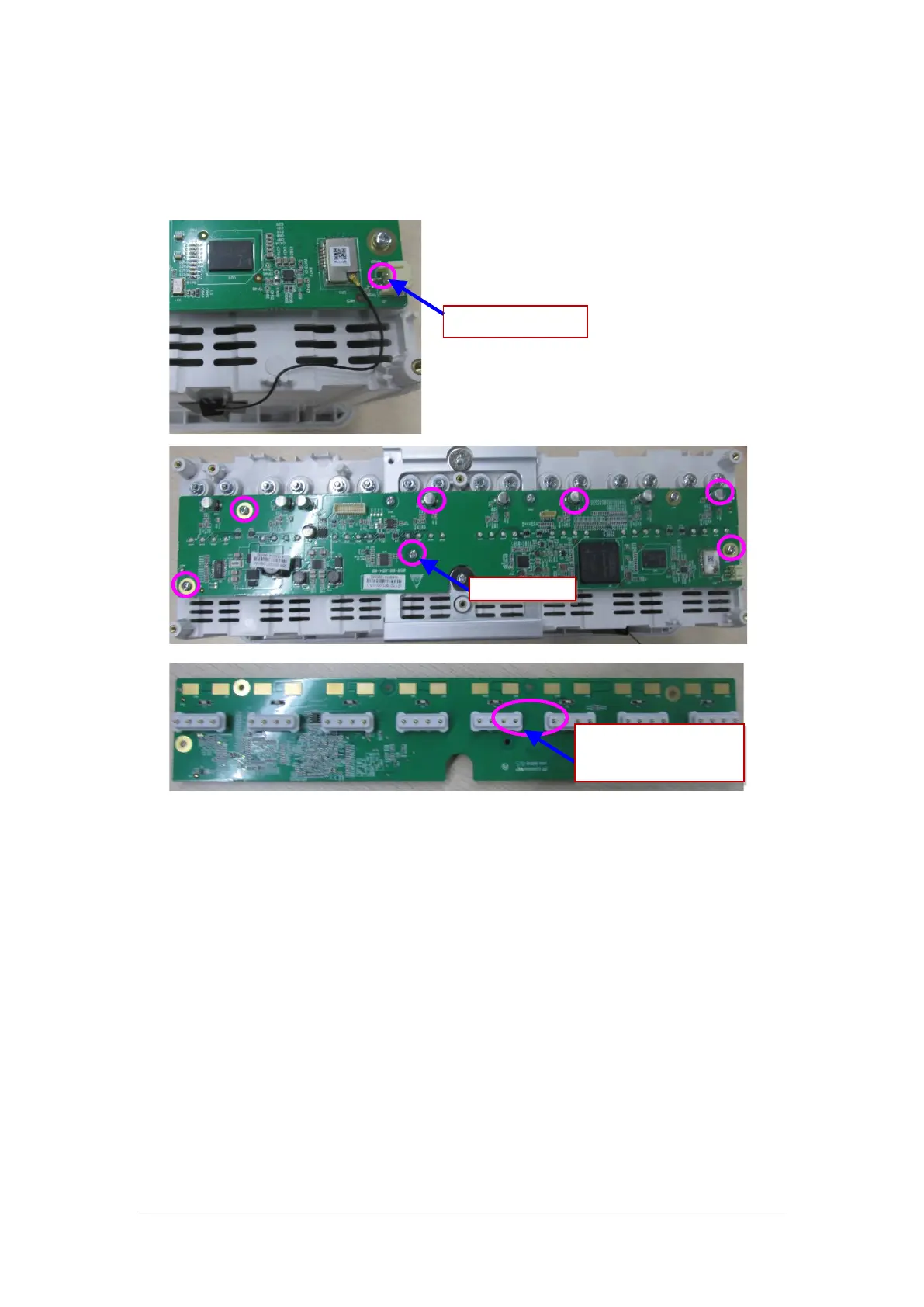
Loosen and remove the seven M3X8 cross recessed pan head screws on the internal module rack
COMM board, and remove the eight POGO PIN silicon cases from the module rack.
Module rack antenna
M3X6 screw
POGO PIN silicon cases of
module rack

Table of Contents

Other manuals for Mindray BeneVision N12

Questions and Answers:

Question and Answer IconNeed help?

Do you have a question about the Mindray BeneVision N12 and is the answer not in the manual?

Mindray BeneVision N12 Specifications

General IconGeneral
BrandMindray
ModelBeneVision N12
CategoryMedical Equipment
LanguageEnglish

Related product manuals