7-32 Structure and Assembly/Disassembly
connecting cables outwards and ground lines to remove the power input module.
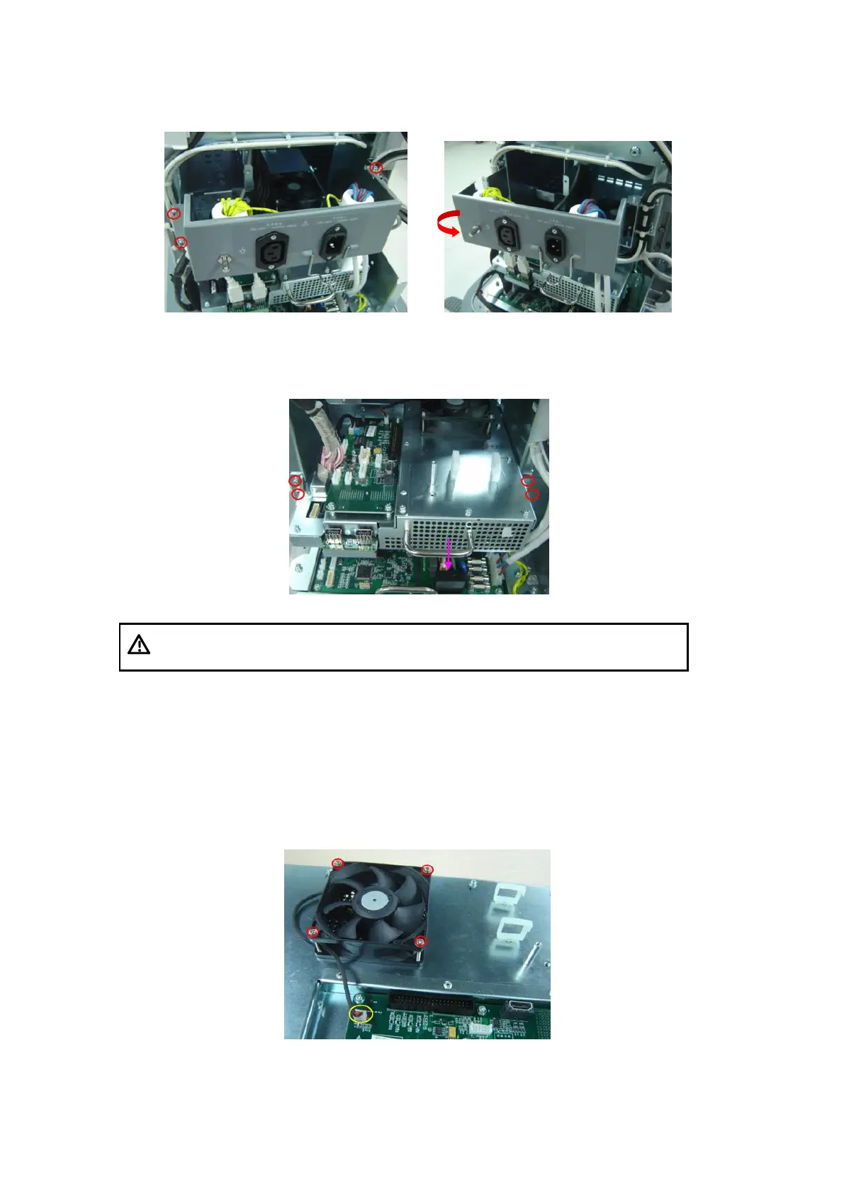
Figure 7-20 and figure 7-21 power input module disassembly figure (1) (2)
4. Pull out the cable plug connecting the main unit module, remove the M3X8 screws (4
pcs) fixing the main unit, grasp the handle to pull out the main unit assembly.
Fig 7-22 Disassemble the Main Unit assembly
Before you disconnect the HDD SATA cable, press the
SATA cable lock.
After removing the monitor assembly, you could do the steps as described in the
following.
7.4.6.1 Main Unit Fan
Remove the fan fixing screws (4 pcs) using the cross-headed screwdriver in a proper
size (the screw types are M3X25, as shown in figure 7-23; and M3X10, as shown in
figure 7-24), pull out the cable plug connecting fan and IO interface board, and then the
main unit fan can be removed.
Fig 7-23 Disassemble the Main Unit fan