Structure and Assembly/Disassembly 7-33
Figure 7-24 Disassemble the Main Unit fan
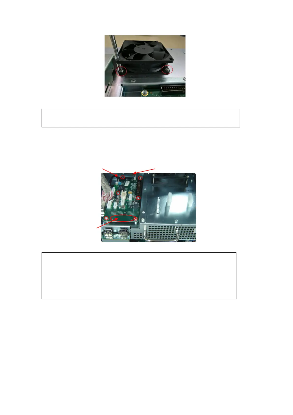
7.4.6.2 IO Interface Board
Remove the M3X8 screws (6 pcs) fixing IO interface board, pull out the two plugs, and lift
upwards to remove the IO interface board.
Signal line from main board to
IO interface board keyboard fan connecting line
Figure 7-25 IO interface board disassembly
The IO interface board and main board are connected by
board-to-board connection, which may be removed forcefully,
you need to grasp the board edge using fingers, and take great
care when pulling out (Refer to the action point).
When connect the IO interface board to the main board, please
take care and do forcefully to avoid damaging the pins.
7.4.6.3 Probe Connected Assembly and CPU Module Assembly
1. Remove the M3X8 screws (2 pcs) for fixing the DC-DC board shielding cover, pull
out the power cable of DC-DC board to main board upwards as well as the shielding
cover.
2. Remove the IO interface board.(Refer to 7.4.6.2 IO Interface Board)
During installation, pay attention to the main unit fan label, which should
be facing inwards.