7-34 Structure and Assembly/Disassembly
Fig 7-26 Disassemble the Probe Connected assembly (1)
3. Remove the M3X8 screws (12 pcs) on the upper part of the main unit and 2 M3X8
screws at the front side (shown in the image, on the left side) to remove the top
cover.
Fig 7-27 Disassemble the Probe Connected assembly (2)
4. Remove the M3X8 screws (6 pcs) to pull out the probe connected assembly from the
main board.
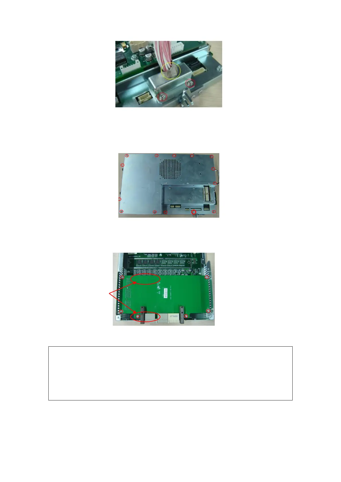
Fig 7-28 Disassemble the Probe Connected assembly (3)
The probe connected assembly and main board are connected by
board-to-board connection, which may be removed forcefully, you
need to grasp the board edge using fingers, and take great care when
pulling out (Refer to the action point)..
When connect the IO interface board to the main board, please take
care and do forcefully to avoid damaging the pins.
5. After removing the top cover, remove the M3X8 (4 pcs) screws to pull out CPU
module assembly upwards.