Hardware Principle 4-9
Support circuit module or function
CPU module, Monitor, Fan, Control panel,
DVD-RW
HDD, Control panel, Front-end of the main
board, Probe board, DVD-RW, Probe, Monitor
Front-end of the main board
Front-end of the main board, back-end of
the main board
Back-end of the main board (FPGA core
voltage)
Front-end of the main board (receiving chip)
Back-end of the main board ( video encoder,
FPGA IO voltage , DDR2)
Back-end of the main board ( video encoder,
FPGA IO voltage)
Probe board (high-voltage switch), 192-array
probe
Probe board (high-voltage switch), 192-array
probe
Transmitting high-voltage
Transmitting high-voltage
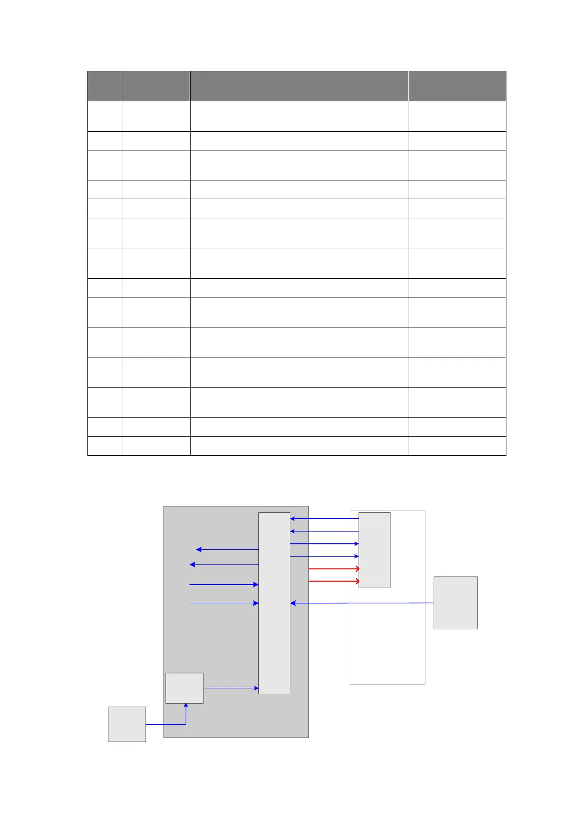
4.3.2 System Power-on Control
CPU
module
PWR_BTN_N
+12V
S3_N
S4_N
CPU_PWR_BTN_N
PWR_OK_N
5VSTB
Power
manag
ement
FPGA
AC-DC
Power
board
12V
AC
online
signal
DC-DC power board
Main board
Control
panel
PWR_12V_EN
PWR_5VSTB_EN
PWR_5VSTB_OK_N
PWR_12V_OK_N