Structure and Assembly/Disassembly 9-49
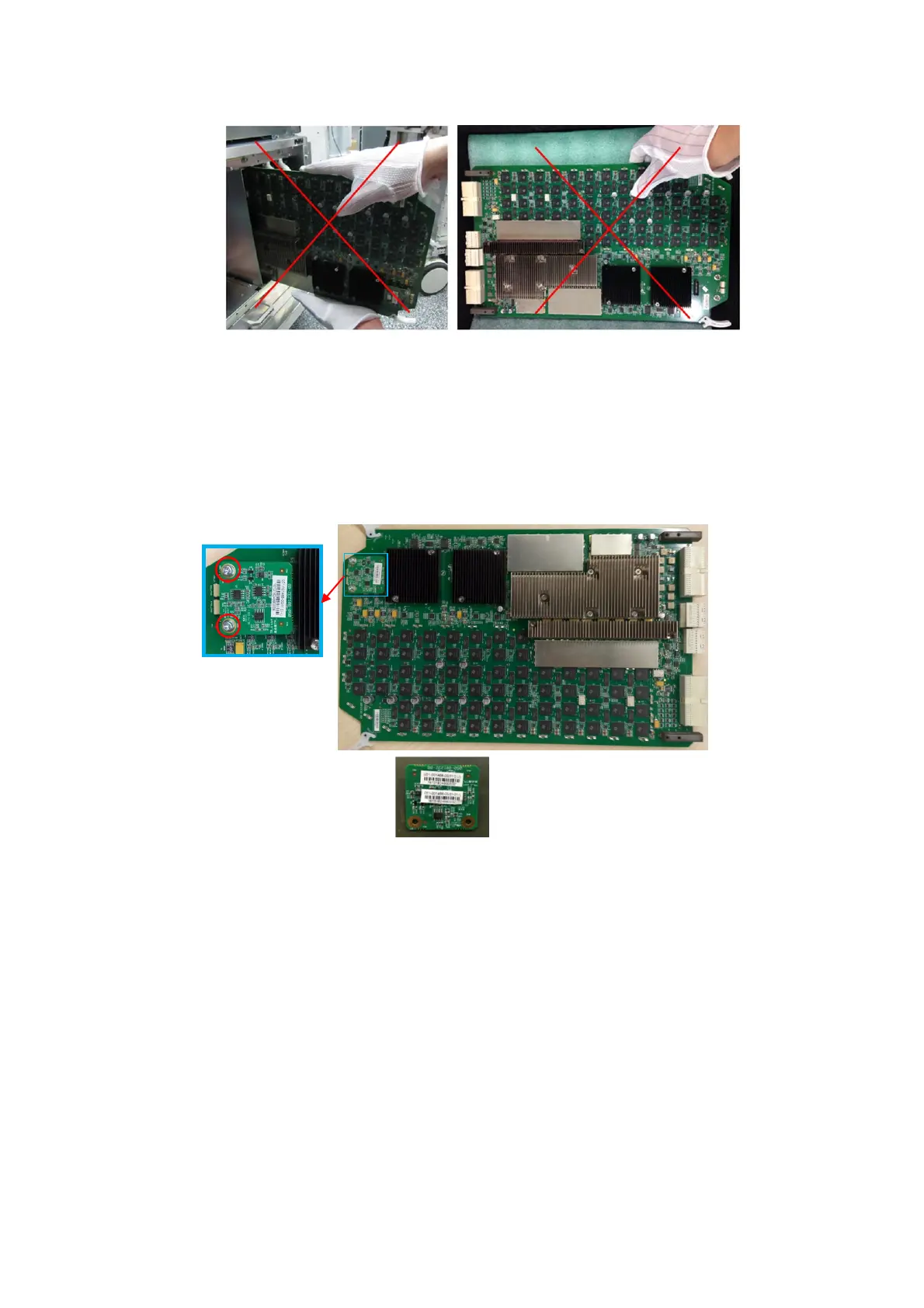
9.3.24.2 CW Assembly
1. See 9.3.24.1 TR 64 PCBA for details.
2. Unscrew 2 M3 X 8 cross panhead screws from the CW assembly (if machine only contains one
CW assembly, only the second TR board is equipped with CW board; If machine has three CW
assemblies, CW assembly should be removed from every TR64 board.) with the screwdriver
(M3, M4) to remove the CW assembly.
9.3.24.3 Engine Board PCBA
1. See Chapter 9.3.16 Main Unit Rear Cover Assembly and 9.3.17 Main Unit Left Cover
Assembly for details.
2. Unscrew 12 M4 X 12 cross panhead screws to remove two shield cover of the machine.