2 - 10 Operator’s Manual
2 System Overview
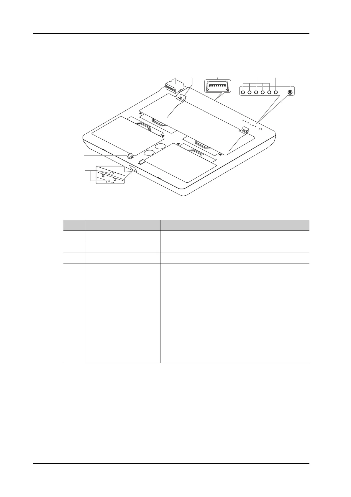
2.8.1 Parts and Names
Figure 2-2 U-Bank
No. Name Description
1. Power connector Connects to the power input port of the system.
2. Tabs Used for fixing the U-Bank to the system.
3. Charging input port Connects the power adapter.
4. Capacity indicators (L1~L5) Indicates the power of the U-Bank.
• The L1-L5 indicators remain on: fully charged or >
80%.
• The L1-L4 indicators remain on: 60% < remaining
capacity ≤ 80%.
• The L1-L3 indicators remain on: 40% < remaining
capacity ≤ 60%.
• The L1-L2 indicators remain on: 20% < remaining
capacity ≤ 40%
• The L1 indicator remains on: 10% < remaining
capacity ≤ 20%
• The L1 indicator blinks: remaining capacity ≤ 10%
8
7
12 3 4 56
L1 L2 L3 L4 L5