9-8 Structure and Assembly/Disassembly
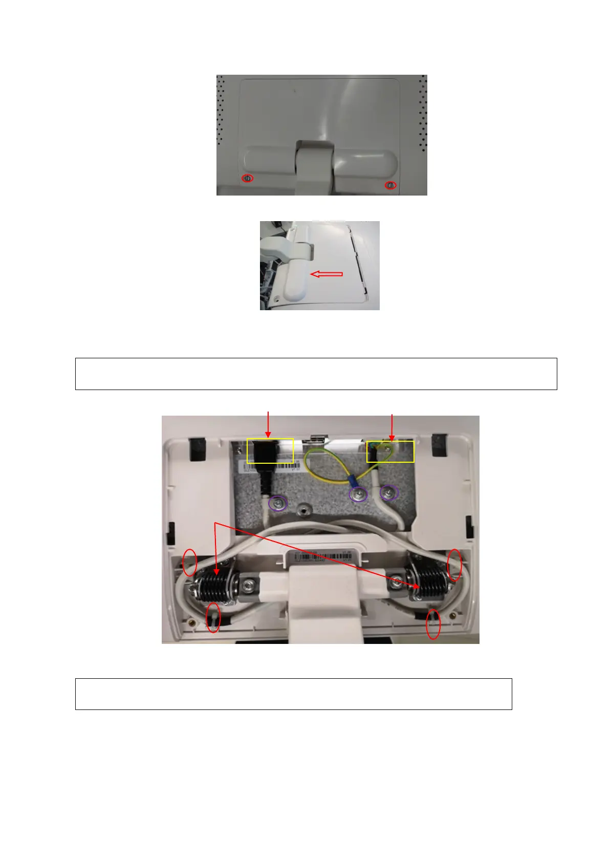
3. Remove the cable cover towards arrow’s direction.
4. Cut off the 4 cable ties with diagonal cutting pliers. Unscrew 3 M4 X12 cross panhead screws
to pull the signal cable and the power supply cable out with cross-headed screwdriver (M3,
M4).
See the figure below for installing the cable anticlockwise. The cable should keep
distance with the damping axis.
5. Unscrew 6 M4 X12 cross panhead screws from the assembly board with the screwdriver (M3,
M4) to remove the display assembly towards the arrow’s direction.
When conducting the operation, please hold the support arm with one person
in case of the falling of the support arm assembly.
ower supply cable
le

 Loading...


