9-60 Structure and Assembly/Disassembly
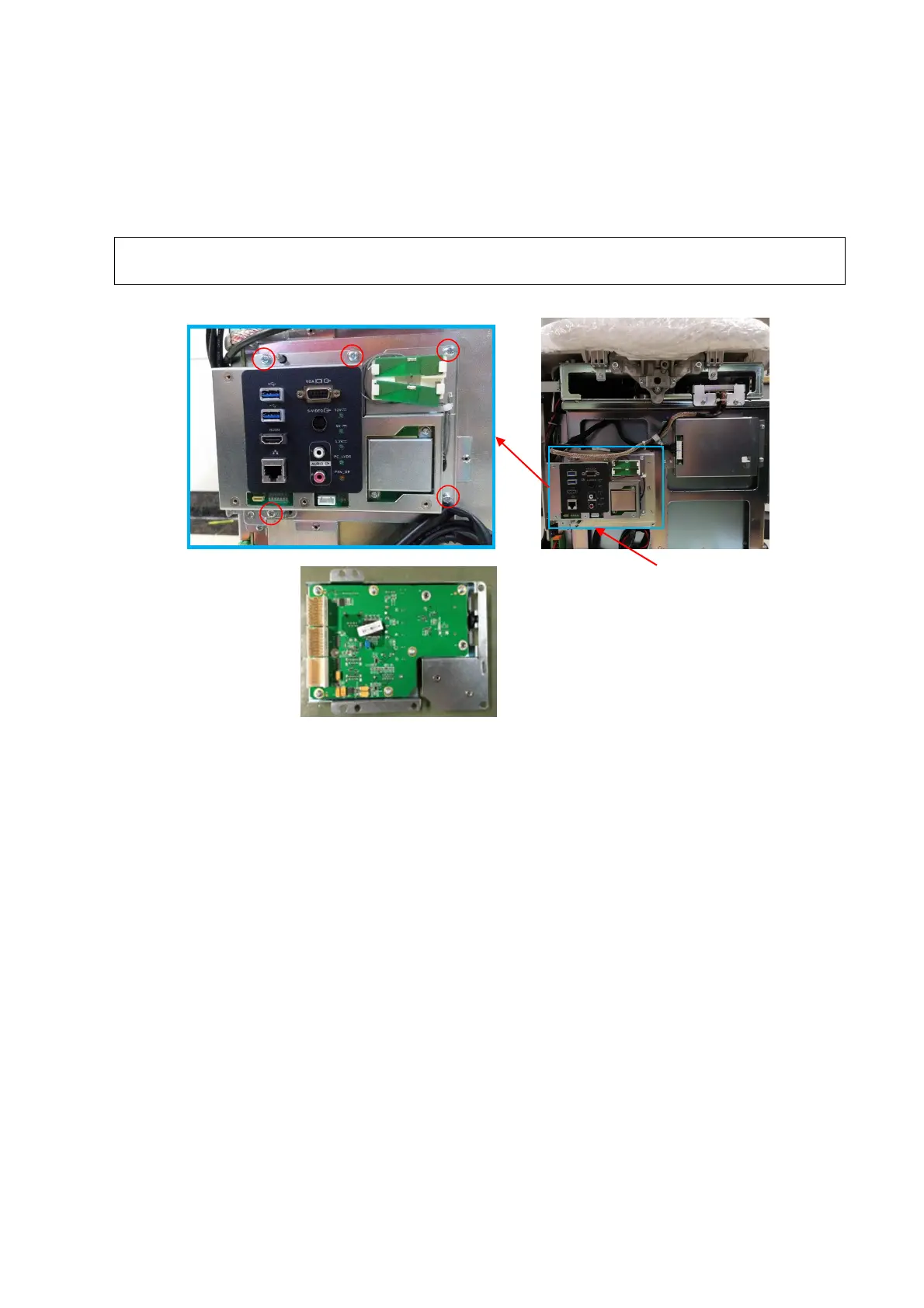
9.3.29 IO Assembly
1. See Chapter 9.3.16, Chapter 9.3.26 and Chapter 9.3.27 for details.
2. Unscrew 5 M4 X 12 cross panhead screws from IO assembly with the screwdriver (M3, M4) to
pull the IO assembly out of the main board slot (FRU).
NOTE:
Avoid applying pressure to the cable hidden behind the IO assembly when installing
IO assembly.
9.3.30 Probe Board Assembly
The disassembly tool: cross-headed screwdriver (M3, M4).
1. See 9.3.19 for details.
2. Step on the brake pedal and the walking pedal. Unscrew 2 M4 X12 cross panhead screws with
the screwdriver (M3, M4) to remove the protective board.
international (FRU)
cables during installation

 Loading...


