Product Principle 4-5
4.2.3 Engine Board
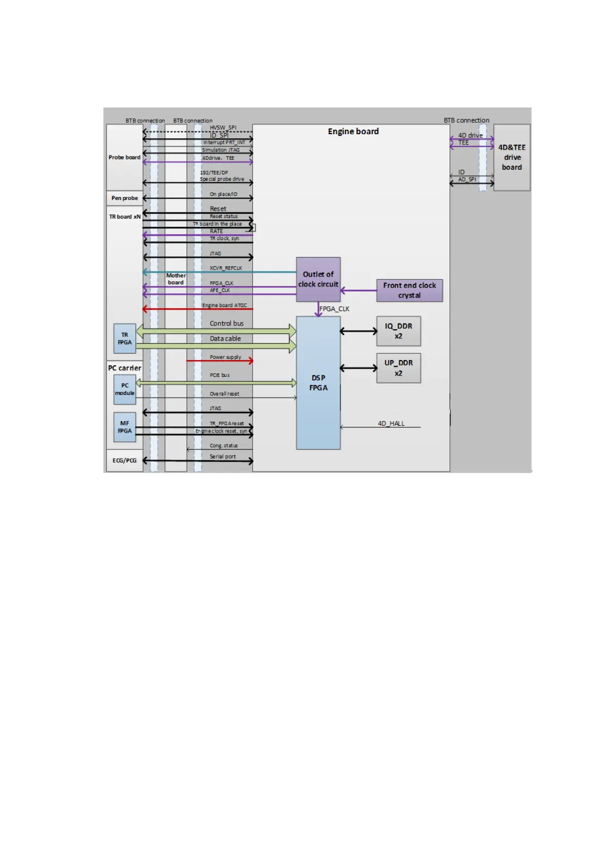
Figure 5 Principle Diagram of Engine Board
The hardware circuit of engine board is shown in the figure above.
Function:
Distribute the clock.
Provides the control and management function of probe related.
a) Probe online, IDs, hot-plug.
b) Control of interior circuit of the probe, such as high-voltage switch, parallel turning, Cable
Driver, etc.
Corresponding control signal of the probe board:
a) Control of the high-voltage (only applicable for the physical channel less than 128, Plato is
not equipped with the function).
b) Configuration of the CPLD on the probe.
c) SPI communicate with probe
Responsible for the module resetting, online upgrade, the management of module information.
Communication and control of the accessories related with image scan, the accessories
include:
a) 4D driving function module; it is an optional independent module, which belongs to the
engine board.
b) Physiological signals function module.

 Loading...


