EasyManuals Logo

Mindray uMEC10 Service Manual

Mindray uMEC10
32 pages
To Next Page IconTo Next Page
To Previous Page IconTo Previous Page
Page #8 background imageLoading...
Page #8 background image
2.2.2 External Connectors
On the back of the patient monitor
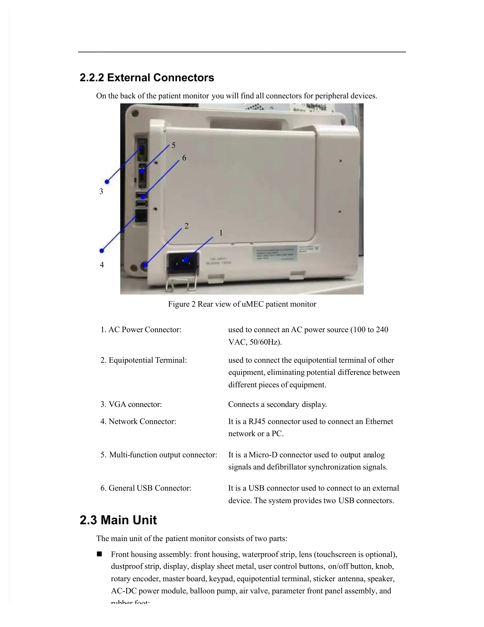
you will find all connectors for peripheral devices.
Figure 2 Rear view of uMEC patient monitor
1.
AC
Power
Connector:
used
to
connect
an
AC
power
source
(100
to
240
VAC, 50/60Hz).
2.
Equipotential
T
erminal:
used
to
connect
the
equipotential
terminal
of
other
equipment, eliminating potential
differenc
e between
different pieces of equipment.
3.
VGA
connector:
Connect
s
a
secondary
displa
y
.
4.
Network
Connector:
It
is
a
RJ45
connector
used
to
connect
an
Ethernet
network or a PC.
5. Multi-
function
output
connector:
It
is a
Micro-D
connector
used
to out
put an
alog
signals and defibrillator synchronization signals.
6.
General
USB
Connector:
It
is
a
USB
connector
used
to
connect
to
an
external
device. The system provides two
USB connectors.
2.3 Main Unit
The main unit of the
patient monitor consists of two parts:
Front housing assembly: front housing, waterproof strip, lens (touchscreen is optional),
dustproof strip, display, display sheet metal, user control buttons,
on/off button, knob,
rotary encoder, master board, keypad, equipotential terminal, sticker
antenna, speaker,
AC-DC power module, balloon pump, air valve, parameter front panel assembly, and
rubber foot;
2
1
5
6
3
4

Other manuals for Mindray uMEC10

Questions and Answers:

Question and Answer IconNeed help?

Do you have a question about the Mindray uMEC10 and is the answer not in the manual?

Mindray uMEC10 Specifications

General IconGeneral
Resolution800 x 600
ECG3/5-lead ECG
EtCO2Optional
BatteryRechargeable lithium-ion
Battery Life4 hours
Dimensions110 mm
AlarmAudible and visual alarms
Power SupplyAC 100-240V, 50/60Hz
AgentNo
O2No

Related product manuals