7
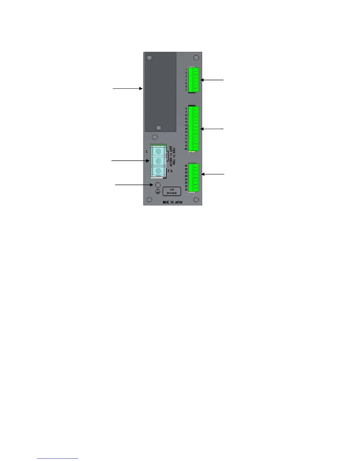
1-2. Rear Panel
(1) Power supply terminal board
Connected to the AC power supply and grounding wire.
(2) Protective ground terminal
Connect this to ground to eliminate noise effects such as static electricity. Do not connect any wires
other than the grounding wire.
This connector is internally linked to F.G. on the power supply terminal board.
(3) External control input/output connector
Used to connect the external control device.
(4) Torque transducer/rotation speed detector connector
Connect the signal cable to the torque transducer/rotation speed detector (MP-9820).
(5) Analog output connector
Connect the signal cable to the analog input device.
(6) Optional part mounting section
One optional part (RS-232C, RS-422/485, PROFIBUS, or CANopen) can be mounted.
(1) Power supply
terminal board
(2) Protective
ground terminal
(6) Optional part
mounting section
(3) External control
input/output connector
(4) Torque transducer/rotation speed
detector connector
(5) Analog output connector