User Manual
2021 Page 14
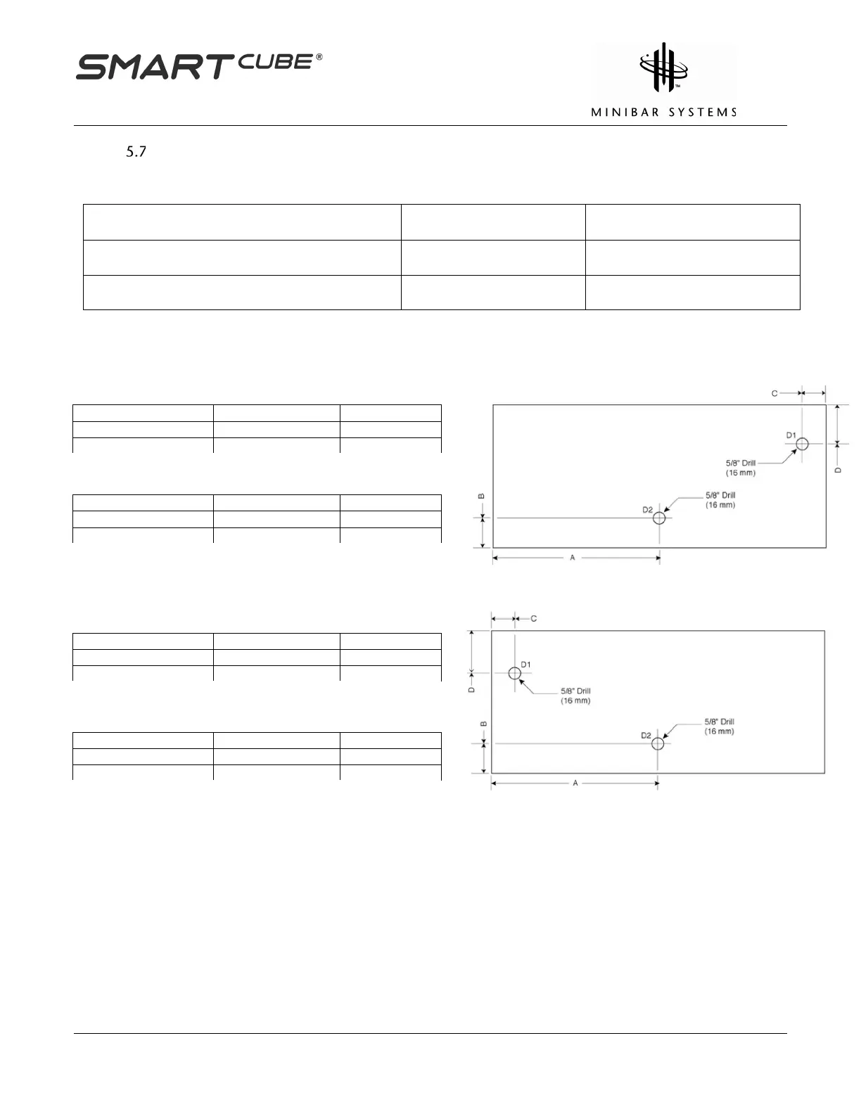
Diagram B – Cable Hole Placement for a Single Tray and Optional Electronic
Lock
D1 – Optional Electronic Lock
D2 – Ambient Snack Tray
5/8” (16 mm)
1
Left Hinge Bar
Right Hinge Bar
Notes
•
Dimensions are in inches and millimeters
•
*Depends on tray placement in cavity. Contact Minibar Systems for assistance.
•
See Section 3.3 if using multiple trays, hole placement may vary
•
All dimensions are internal
•
All tolerances 0.12” (3 mm)
•
Roller catches are not required if optional electronic lock is used
•
Not to scale
D2 Hole Placement
A*
B
D2 Hole Placement
A*
B