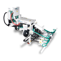
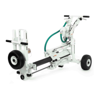
The Minnich A-4SC/A-5SC is a self-propelled, on-slab multiple dowel pin drill designed for concrete drilling applications. It is capable of both horizontal and vertical drilling, with skew drill bed and on-grade kit options available. The unit is designed to be towed by an air compressor.
Technical Specifications:
- Drill Steel Shank: 0.875" x 4.25" (22.2mm x 107.9mm)
- Drill Steel Length U.C.: 24" (61.0cm)
- Drill Bit Diameter: 0.625" - 2.50" (15.9mm to 63.5mm)
- Maximum Drill Depth: 18" (45.7cm)
- Drill Distance From Top of Slab: 3.5" - 12" (8.9cm to 30.5cm)
- Minimum Cutout Width: 48" (121.9cm)
- SCFM Required Per Drill: 92.2 (43.5D m³/sec)
- PSIG Required: 110 (7.58 BAR)
- Weight A-4SCW (basic): 3260 lbs. (1433 kg)
- Weight A-5SCW (basic): 3460 lbs. (1569 kg)
Environmental Conditions:
- Operating Temperature: +5°C to +40°C (+41°F to +104°F)
- Humidity: 50% RH at +40°C (+104°F), (90% RH at +20°C (+68°F))
- Altitude: 1000m (3280ft) above mean sea level
- Storage Temperature: -25°C to +55°C for 24 hours (-13°F to +131°F)
- Ingress Protection: IP2X
- Sound Levels: Approximately 85 dBA and 85 dBC (hearing protection required)
Usage Features:
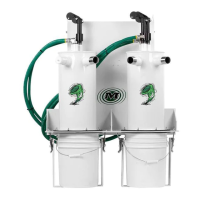
The A-4SC/A-5SC features power crab steering, power steering, power brakes, and solid rubber tires for maneuverability. It includes a hole spacing pointer and adjustable drill height, depth, and centers for precise drilling. An auto control system is integrated for efficient operation, and dust collection is available as an option. The unit is capable of towing an air compressor.
Drill Steel and Bits:
The manual outlines three types of drill steel and bits:
- 2 Piece Taper Steel and Bit: Utilizes a shim for seating the bit.
- 1 Piece Steel and Bit (Whirly Bit): A single-piece design.
- "H" Thread Steel and Bit: Features a threaded connection.
Drill steel and bits are intended for concrete drilling only and are not suitable for drilling through steel mesh, rebar, or dowel bars, as this will void warranties and shorten bit life. Bit life is also influenced by bit sharpness, aggregate type, and concrete condition.
General Notes on Drill Steel and Bits:
- Maximum bit diameter for hydraulic drills is 2" (50.8mm).
- Maximum bit diameter for pneumatic drills is 2 1/2" (63.5mm).
- Smallest hole diameter is 5/8” (16mm).
- Cutting speed ranges from 15 to 30 seconds for a 6" (152.4mm) deep hole, depending on bit diameter and aggregate.
- Average bit life: 180 holes, 9” (228.6mm) deep per bit.
- Average drill steel life: 600 holes, 9” (228.6mm) deep per drill steel.
- Removable bits are carbide and cannot be re-sharpened.
- Whirly bit steel can be re-sharpened twice.
Drill Bit Installation:
- Ensure the hole through the center of the drill steel is clear.
- Clean the tapered end of the drill steel and the inside of the drill bit with a non-oily cleaner.
- Verify a brass shim is in the drill bit; if not, carefully roll and insert a new one without overlap.
- Place the drill bit on the tapered end of the drill steel and tap it on a firm surface to seat it.
Drill Bit Removal:
- Swing the latch to allow drill steel removal.
- Pull the drill steel out of the drill.
- Use two hammers: place one on the bottom side of the bit and strike the top side with the other. Rotate the drill steel 1/4 turn and repeat until the bit comes off.
- CAUTION: Bit may pop off with force.
Operation Procedure:
- Safety First: Wear proper safety equipment. Be aware of flying debris, dust, loud noise, and pinch points.
- Operator Position: Stand at least 10 feet (3 meters) from the machine with good visibility.
- Feed Lever: Place in the "in" position to move bits against the slab.
- Drill Lever: Place in the "on" position to activate drill motors. Press the initiate lever if equipped.
- Depth Reached: When the required depth is reached, place the feed lever in the "out" position.
- Clear Hole: When drill steel is clear, place the drill lever in the "off" position.
- Wireless Control: Drills automatically retract and shut off when hole depth is reached.
- Repositioning: Release the brake (if equipped), reposition the drill, and reset the brake.
- Steering: Turn the wheel or use the joystick to steer.
- Crab Feature: For units with the "crab" feature, turn it "on" and steer to keep the machine tight against the slab while repositioning.
Maintenance Features:
- Lubrication: The lubricator should be filled with proper lubricant. Recommended lubricants for rock drills vary based on ambient temperature (e.g., AGIP RD100, Caltex Rock Drill, Texaco Lube 46, Chevron Vistac Oil 32X, Mobil Almo Oil No. 1, Shell Tona Oil R100). DO NOT USE ENGINE OIL, DIESEL, OR HYDRAULIC FLUID.
- Regulator Maintenance: The pressure regulator can be disassembled for servicing without removal from the pipe line. Parts should be cleaned with warm water and soap, inspected for damage, and replaced as needed. O-rings should be lubricated with silicone-based grease during reassembly.
- Lubricator Maintenance: The lubricator should be kept clean. If oil delivery drops, clean the siphon tube inlet filter, Flow-Guide® variable orifice screw, and needle and seat. Drain contaminants from the bowl. Lubricate o-rings with Parker O-Lube. Clean plastic bowls with a clean, dry cloth only.
- Cylinder Service Kits: Available for both Oversize Rod Cylinders (Feed) and Standard Rod Cylinders, with specific part numbers for various rod diameters and bore sizes. Obsolete style cylinders with snap ring bushings are no longer supported for service parts.
Safety Decals:
The manual details the placement of various safety decals, including:
- "PINCH POINT KEEP AWAY"
- "CLEAN DRILL STEEL TAPER WITH NON OILY SUBSTANCE BEFORE INSTALLING NEW DRILL BIT"
- "NOISE MAY DAMAGE HEARING, WEAR PROPER HEARING PROTECTION"
- "FLYING PARTICLES MAY CAUSE EYE INJURIES, WEAR PROPER EYE PROTECTION"
- "DUST CAN CAUSE INJURY TO YOUR HEALTH, IF VENTILATION IS INADEQUATE USE AN APPROVED RESPIRATOR"
- "HIGH PRESSURE, KEEP AWAY FROM LEAKS, BLEED DOWN BEFORE REMOVING LINES FOR SERVICE"
- "KEEP GUARDS IN PLACE, DISCONNECT POWER BEFORE SERVICING"
- "INSTALL LOCK PIN PRIOR TO TRANSPORTING MACHINE"
- "BE SURE SUPPLY LINES ARE SECURE, DO NOT EXCEED 120 PSI (8.25 BARS) OR DAMAGE TO MACHINE AND OR BODILY HARM MAY RESULT"
- "STAND CLEAR WHEN RAISING OR LOWERING"
- "MACHINE NOT EQUIPPED WITH PARKING BRAKE"
- "DRILLS WILL AUTOMATICALLY START WHEN AIR SUPPLY IS LOST AND REAPPLIED"
- "CAN TETHER ONLY"
- "HIGH PRESSURE, BLEED AIR PRESSURE BEFORE SERVICING"
These decals provide critical warnings and instructions for safe operation and maintenance of the device.