16
Mechanical and Chassis Installation
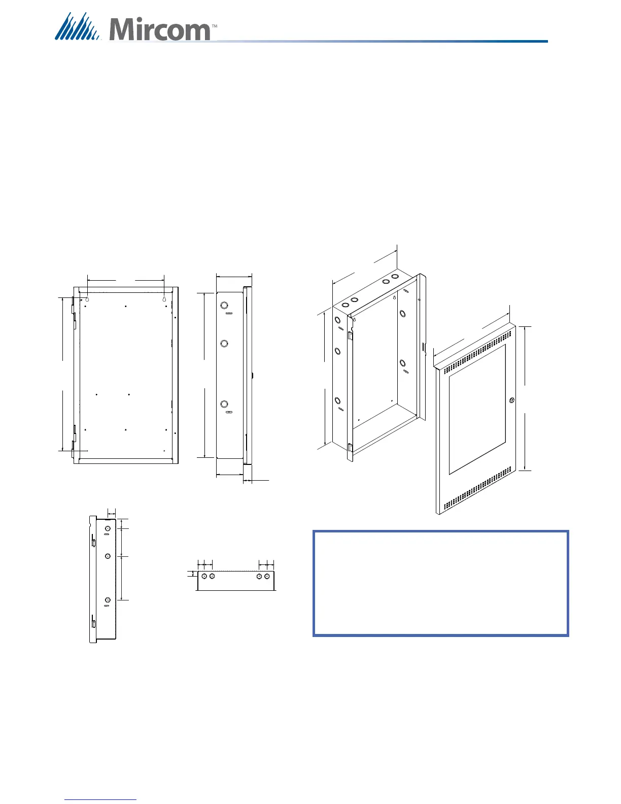
4.1.4 UB-1024DS and DOX-1024DS/R Mechanical Installation
The universal enclosure is suitable for flush or surface mounting, and have a built-in trim ring.
Figure 4 UB-1024DS and DOX-1024DS/R Installation Instructions and Dimensions
Dimensions of backbox (minus built in trim ring) 26” x 14.5” x 4.25”
Distance between horizontal mounting screws 12”
Distance between vertical mounting screws 23.5”
Complete Dimensions of Enclosure with door 28” x 17” x 5.6”
26 ”
17”
23 1/2”
14 1/2”
5 5/8”
1 3/8”
4 1/4”
12”
28 ”
26 ”
1 3/4”
1 3/4”
6”
2”
9 1/2”
1 3/4”
1 3/4”
2”
2”
TOP VIEW
SIDE VIEW
SIDE VIEW
BACKBOX
DOOR
BACKBOX FRONT VIEW
UB-1024DS UNIVERSAL BACKBOX AND DOX-1024DS/R DOOR
KNOCKOUT LOCATIONS
Dimensions of backbox (minus built-in trim ring)
Horizontal distance between mounting screws
Vertical distance between mounting screws
Complete dimensions of enclosure with door
Size of Knockouts
26”H x 14 1/2”W x 4 1/4” D
12”
1”
23 1/2”
28”H x 17”W x 5 5/8”D