60
Indication & Controls
6.0 Indication & Controls
This chapter describes the LED indicators and controls of the FX-3500.
6.1 Indication and Controls
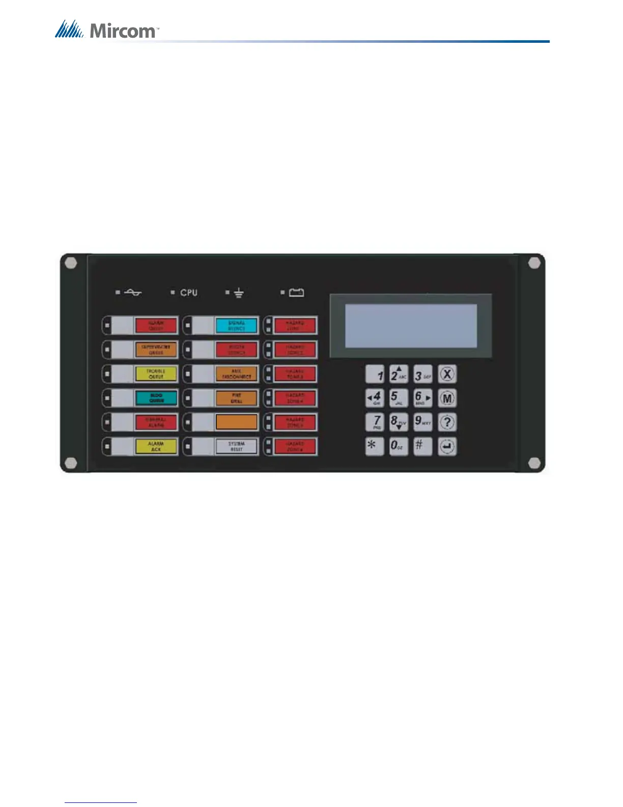
FX-3500 Display Panel is equipped with the following
• 12 Control buttons with associated LEDs
• 16 button Numeric Keypad with Cursor buttons
• 6 Hazard Zones with 2 LEDs (red and yellow) each
Figure 10 displays the LED indicators and the control button on the FX-3500 main board.
Figure 10 LED Indicators and Control Buttons
The FX-3500 has the ability for 2 additional RAX-1048TZDS. Each RAX-1048TZDS Display
Adder Module provides annunciation for up to 48 Zones. Each LED zone has two LEDs.
• 1 Red/Yellow Alarm/Supervisory LED.
• 1 Yellow Trouble LED.
6.2 LCD Display
The display is a four line, 20 character back-lit alphanumeric LCD. It displays information
regarding the panel, its circuits, and devices. An on-screen cursor is controlled by the cursor
buttons for menu selection and control. Report information provided by the LCD display
includes:
• Alarm Log
• Event Log
• Current Levels
• Device Information
• Verification and Maintenance Reports