32/1531-ANF 901 43 Uen B2 2016-04-01
Installation Guide
Base Station
20
3.2.6 SECURE THE CABLE
For safety reasons secure the base station cable to a convenient point at about 30 cm
from the base station.
If for some reason the base station drops, it is secured by the cable.
3.2.7 PINNING
1 Cut the cable to the correct length and connect the cable to a RJ45 modular jack.
2 For information on the pinning of the data jack see the following:
• IPBS, Pin the IPBS Cable on page 20.
• BS3x0 and BS3x2, Pin the BS3x0/BS3x2 Cable on page 21.
Do not plug the connector in the base station yet!
NOTE: Since the distance between the base station and the wall is limited, a RJ45
modular jack without cable retention must be used.
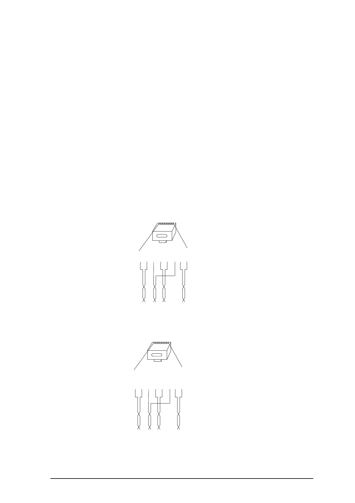
Pin the IPBS Cable
Figure 11. Connector pinning of the LAN/PoE connector, power feed over the
spare cable pairs.
Figure 12. Connector pinning of the LAN/PoE connector, power feed over the
Rx/Tx data cable pairs.
RJ45
modular jack
Tx
Tx
Rx
Pwr
Pwr
Rx
Pwr
Pwr
Pwr = Power pairs
Rx = Reciever data pair
Tx = Transmitter data pair
014
15432678
RJ45
modular jack
Tx/Pwr
Tx/Pwr
Rx/Pwr
Spare
Spare
Rx/Pwr
Spare
Spare
NC
=
Not Connected
Rx/Pwr
=
Reciever & power pair
Tx/Pwr = Transmitter & power pair
015
15432678