MELSEC-A
1. INTRODUCTION
1 - 2
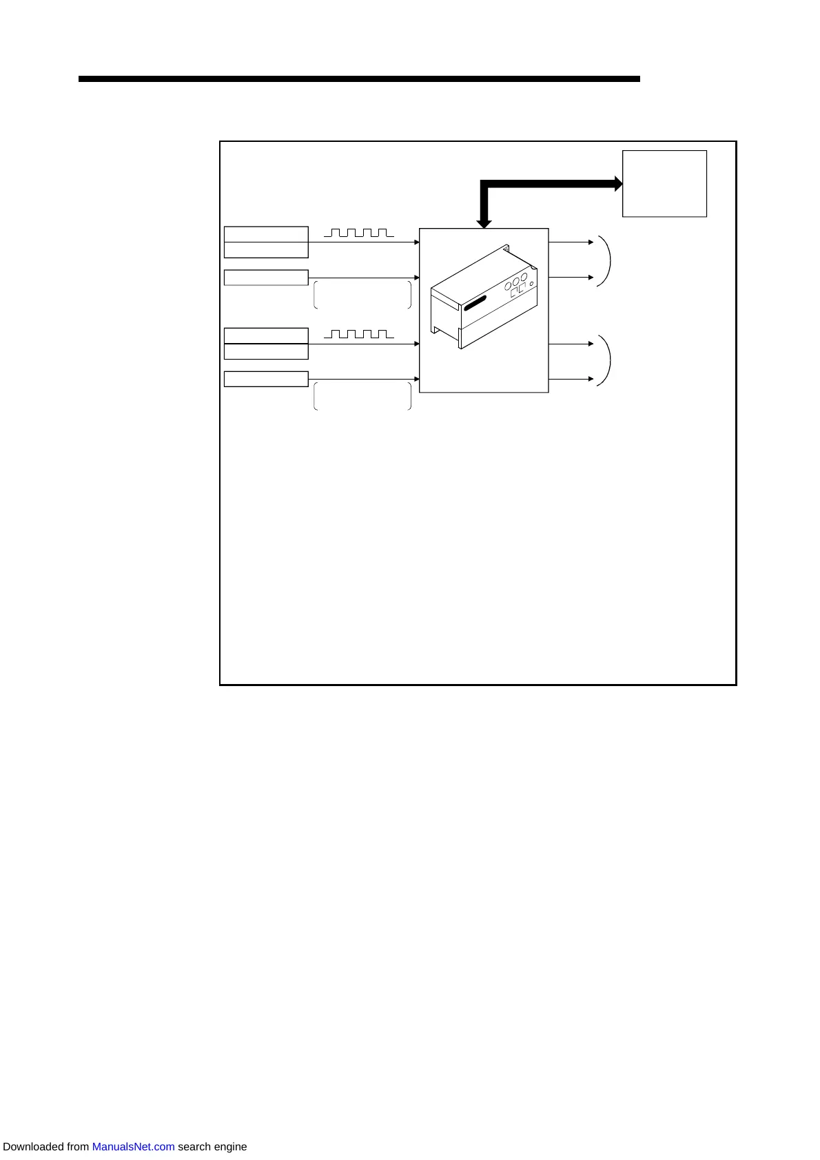
The following diagram outlines how the high-speed counter module operates.
Pulse generator
Encoder
Pulse
Controller
To CH1
1)
2)
To CH2
1)
2)
4) I/O signal
Master module
Pulse generator
Encoder
Controller
Pulse
Preset counter
function selection
Preset counter
function selection
Read/write from/to
remote register
3)
Coincidence output
(2 points)
3)
Coincidence output
(2 points)
High-speed counter module
External
control signal
External
control signal
Only the AJ65BT-D62D-S1 accepts one input and provides one coincidence
output. However, it can use two points for the counter value magnitude
comparison (coincidence, greater, less) signals.
*
1) Pulses input to the high-speed counter module are counted.
2) The preset or counter function can be selected with an external control signal.
3) The pulse is compared as a coincidence output with the present count value
and a signal is issued accordingly.
4) The sequence program can be used to confirm the I/O signals and remote
register status of the high-speed counter module and to start, stop and preset
the counter.
Downloaded from ManualsNet.com search engine
 Loading...