MELSEC-A
5. PULSE INPUT AND COUNTING METHOD
5 - 2
5.1 1-phase pulse input
In 1-phase pulse input, multiplication by one or two can be selected for counting.
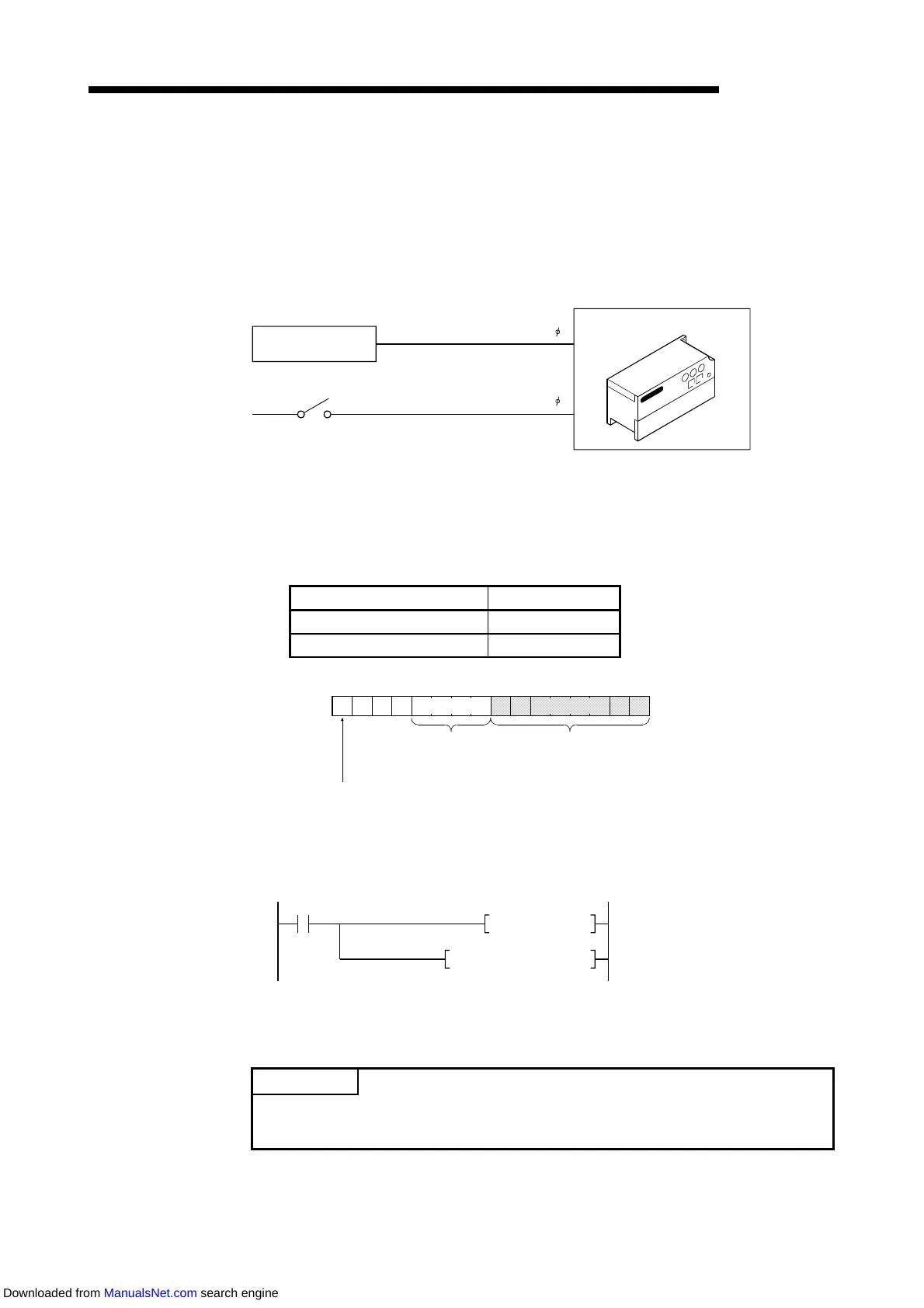
(1) Relationship between phase A pulse input and down count command
The following diagram shows the relationship between phase A pulse input and
down count command.
High-speed counter module
Encoder
Pulse input
To A
Down count command
{or RY(n+1)3 (RY(n+1)A) on}
To B
(2) Counting mode setting
To use this counting mode, set the following value to the lower 8 bits of the remote
register {address RWwm+2 (RWwm+A)} using the sequence program.
When the value set is not the following set value, the initial value (1-phase
multiplication by one) is set.
Counting Mode Set Value
1-phase multiplication by one 00H
1-phase multiplication by two 01H
000
4 bits 8 bits
015
Counter function
selection register
(Refer to Chapter 9)
External output hold/clear setting
0: Clear
1: Hold
Refer to A
endix 1
Address
RWwm+2(CH1)
RWwm+A(CH2)
Set in hexadecimal.
Pulse input mode register
[Sequence program example]
• Counting in 1-phase, multiplied-by-two mode
Write command
MOV
TO
H0001 D0
H
×
H
◎
D0 K1
×
: First I/O number of master module
◎
: Corresponding station register address of master module buffer memory
POINT
Exercise care when setting the pulse input mode, since the upper 8 bits are used
for the counter function selection register and external output hold/clear setting.
Downloaded from ManualsNet.com search engine
 Loading...