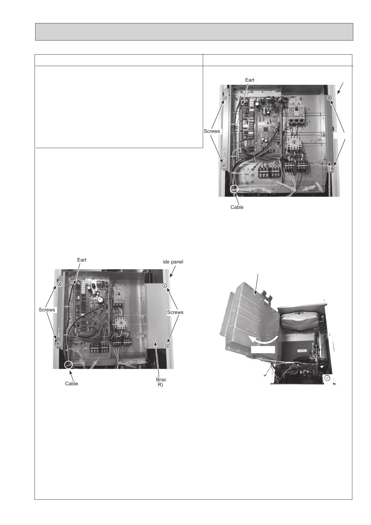
Note: The photo shown is the
ERSE-YM9EE.UK
model.
Cable strap
Earth cable
Bracket
(R)
Side panel
Screws
Screws
Note: The photo shown is the
ERPX-YM9E.UK
model.
65
DISASSEMBLY PROCEDURE
PHOTOS/ FIGURES
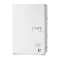
Photo 4-1
Note: The photo shown is the
EHSD-YM9E.UK
model.
4. How to swing the control box to the front
(1) Remove the front panel. (Refer to Procedure 1.)
(2)
Remove the 2 screws from the control box bracket (R) and
the 2 screws from the control box bracket (L). (Photo 4-1
and 4-2)
(3) Disengage the control box bracket (R) from the right-hand
side panel and pull the control box. At this point, lifting
slightly and pulling the control box will swing the control
box to the front. (Photo 4-3)
Note: Disconnect the field wiring as necessary.
Cable strap
Earth cable
Bracket
(R)
Side panel
Screws
Photo 4-3
Control box
Swing
Screws
Photo 4-2
OCH815A