Gasket G1"
66
DISASSEMBLY PROCEDURE
PHOTOS/ FIGURES
Photo 5-1
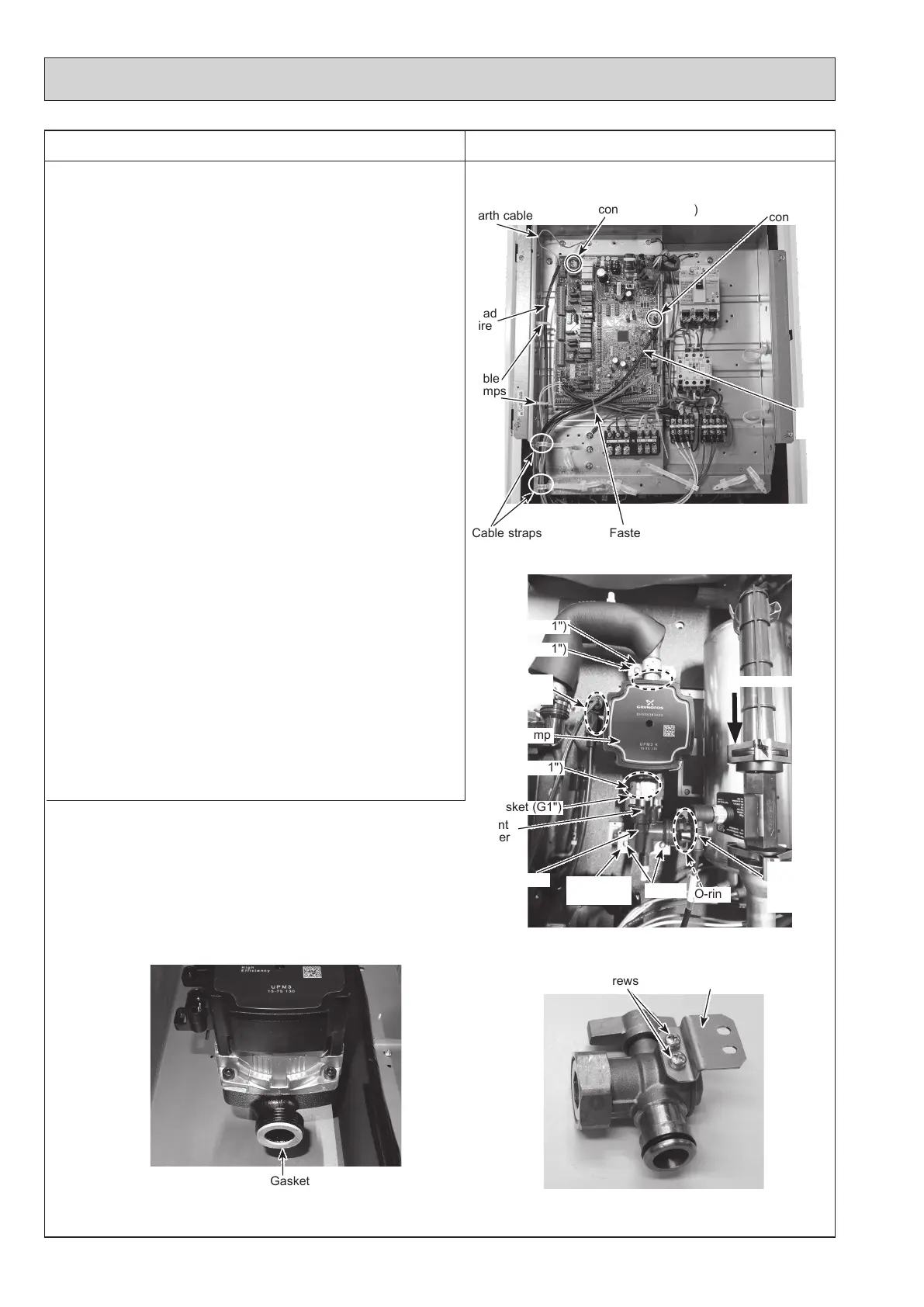
5. How to remove water pump/ pump elbow
<Water pump>
(1) Remove the front panel. (Refer to Procedure 1.)
(2) Disconnect the CNP1 connector, the earth cable, and the
CNPWM connector on the controller board. (Photo 5-1)
(3) <E**** series>
Release the water pump lead wire from the fastener, the
2 cable clamps and the 2 cable straps. Feed the lead
wire out the control box without putting strain on the
CNP1 and the CNPWM connectors. (Photo 5-1)
<ERSE series>
Release the water pump lead wire from the fastener, the
2 cable clamps and the cable strap. Feed the lead wire
out the control box without putting strain on the CNP1
and the CNPWM connectors. (Photo 5-1)
(4)
Swing the control box to the front. (Refer to Procedure 4.)
(5)
<E*SC/D/F series>
Remove the G1" nuts using 2 spanners: one to hold the G1"
nut and the other to turn the other side of G1" nut.
• When reinstalling the G1" nuts, use new G1" gaskets.
(Photo 5-3)
• Set the water pump in the way that the die stamped
arrow facing down, and the lead wire connectors facing
to the left. (Photo 5-2)
• Be sure to change the pump and the water pump lead
wire together.
• Be sure to wipe water around the surface of the pump
and the water pump lead wire thoroughly.
Photo 5-2 (E*SC/D/F series)
Photo 5-3
(E*SC/D/F and ERPX series)
Pump elbow
Water pump
connector (CNP1)
Earth cable
Fastener
Cable straps
Lead
wire
O-ring
CNPWM
connector
Water pump
Nut (G1")
Screws
Gasket (G1")
Lead wire
connectors
Gasket (G1")
Pump
elbow stay
Different
diameter
quick
connection
Photo 5-4 (ERPX series)
Screws
Pump
elbow stay
Flow direction
Cable
clamps
Nut (G1")
Lead
wire
Different
diameter
quick
connection
OCH815A