Introduction
This manual covers the items required for installing, connecting and setting up the Mitsubishi Electric CNC.
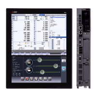
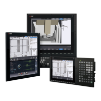
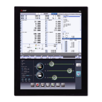
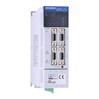
Supported models are as follows:
Abbreviations in this manual are as follows:
Read this manual thoroughly and understand the product's functions and performance before starting to use.
This manual is written on the assumption that all optional functions are added, but the actually delivered device may
not have all functions.
The unit names, cable names and various specifications are subject to change without notice. Please confirm these
before placing an order.
Be sure to keep this manual always at hand.
This manual notes a reference chapter as "Chapter: Section: Paragraph".
(Example) For "4.1.1 Environment Conditions inside the Control Panel" :
"General Specifications: Environment Conditions: Environment Conditions inside the Operation"
("4.1.1 Environment Conditions inside the Operation" included in "4.1 Environment Conditions" of "4 General
Specifications")
Notes on Reading This Manual
(1) This book is configured as follows.
Refer to the following chapters as necessary.
Installation and connection: Chapter 1 to 18
Setup: Chapter 19 to 36
(2) This manual explains general parameters as viewed from the NC.
For information about each machine tool, refer to manuals issued from the machine tool builder.
If the descriptions relating to "restrictions" and "allowable conditions" conflict between this manual and the
machine tool builder's instruction manual, the later has priority over the former.
(3) This manual is intended to contain as much descriptions as possible even about special operations.
The operations to which no reference is made in this manual should be considered "impossible".
(4) The "special display unit" explained in this manual is the display unit incorporated by the machine tool builder,
and is not the MITSUBISHI standard display unit.
(5) This manual is for the machine tool builders who set up the NC system.
(6) The control unit for M80W is mainly used as a control unit to explain the connection, etc. in the drawings on
this manual.
(7) Do not connect to the pin described as "NC" on the pin assignment table of the connector.
(8) The characteristic values and numerical values without tolerances mentioned in this manual are representative
values.
Supported models Abbreviations in this manual
M800W Series M850W, M830W
M80W Series M80W
Abbreviations Supported models
M800, M800 Series M800W Series
M80, M80 Series M80W Series
M800/M80, M800/M80 Series M800W Series/M80W Series
M8, M8 Series M800W Series/M80W Series

 Loading...


