 Loading...
Do you have a question about the Mitsubishi Electric M800W Series and is the answer not in the manual?
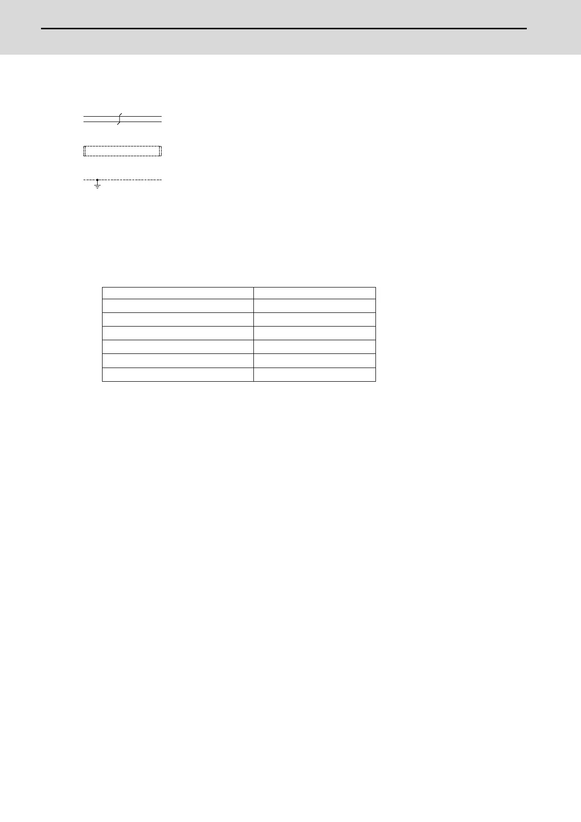
| Number of control axes | Up to 8 axes |
|---|---|
| High-speed processing | Yes |
| Positioning control | Yes |
| Synchronized control | Yes |
| Spindle control | Yes |
| Operating Temperature | 0 to 45°C |
| Storage Temperature | -20 to 60°C |
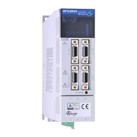
| Control Method | Digital Servo Control |
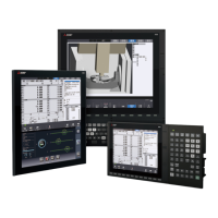
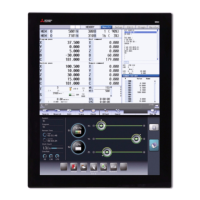
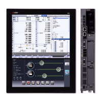
| Display | 15-inch LCD |
| Communication interfaces | Ethernet, RS-232 |
| Power Supply | AC 200 to 240V |
| Type | CNC Control System |