8 Installation In Enclosure
8.6 Connecting Methods for Main Unit and Extension Devices
121
FX3G Series Programmable Controllers
User's Manual - Hardware Edition
1
Introduction
2
Features and
Part Names
3
Product
Introduction
4
Specifications
5
Version and
Peripheral
Devices
6
System
Configuration
7
Input/Output
Nos., Unit Nos.
8
Installation
9
Preparation and
Power Supply
Wiring
10
Input Wiring
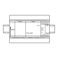
8.6.8 Connecting method G - connection of input/output powered extension unit
This subsection explains the procedures for connecting an input/output powered extension unit.
1 Remove the top cover (A in the right figure)
on the left side of the input/output powered
extension unit.
2 Connect the connector of the provided
extension cable (B in the right figure) to the
extension connector of the unit/block on
the upstream side (left side).
3 Connect the connector of the extension
cable (supplied) (B in the right figure) to the
extension connector of the input/output
powered extension unit to be added.
4 Fit the top cover (A in the right figure).
8.6.9 Connecting method H - connection of extension block to input/output powered
extension unit
This subsection explains the procedures for connecting an extension block to an input/output powered
extension unit.
1 Remove the extension connector cover (A in
the right figure) on the right side of the input/
output powered extension unit.
2 Connect the extension cable (B in the right
figure) from the extension block to be added
(right side) to the extension connector of the
input/output powered extension unit.
• When connecting FX3U-1PSU-5V, read "input/output powered extension unit" as the unit.
• When connecting FX
2N Series input/output powered extension unit FX3U-1PSU-5V, connect the unit to be
added (right side) and the existing unit (main unit) with the supplied extension cable or the optional
extension cable.
3 Fit the extension connector cover (A in the right figure).

 Loading...