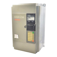
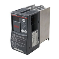
.’
6.3 Method of measuring main circuit voltage;
current and output power
..... . ... . ... ..... ‘31
6.4 Measuring instrument, selection and usage
...............
34
6.5 Transistor modules and diode modules
............... 36
6.6 Parts replacement
............... 38 -’
Q 7. TROUBLESHOOTING
............... 46
7.1 Troubleshooting
.... ..*........ 46
7.2 Protective functions
...............
44
Q 8: SPECIFICATIONS
.................. 51
8.1 Block diagram
................ 51
8.2 Terminals
................ 53
8.3 Standard specifications
............... 58
8.4 External dimensions
...............
64
8.5 Selection of peripheral devices
............... 65
8.6 Drip shield kit
...............
66
. .
8.7 Overload protection
...
.
.
............... 68
r PARAMETER UNIT
I
Q 1.. INSTALLATION
. . . . . . . . . . . . . . . 79
8 2. OUTLINE OF FUNCTIONS
. . . . . . . . . . . . . . . 72
1 Q 3. FUNCTION KEY DESCRIPTIONS
. . . . . . . . . . . . . . . 73
Q 4. OPERATION
. . . . . . . . . . . . . . . 76
4.1 Operation modes
4.2 Operation with external signals
4.3 Operation with PU
....... . ....... 76
............... 77
............... 78
4.4 Common setting errors
see also Page 92
Q 5. SETTINGS OF CONTROL VARIABLES (PARAMETERS)
. . . . . . . . . . . . . . .
81
: . . . . . . . . . . . . . . 83
5.1 Control functions and setting method
.: . . . . . . . . . . . . . 83
5.2 Examples of operation
. . . . . . .i. . . . . . .
85
. .
5.3 Caution (iIlega1 settings)
. . . . . . . . . . . . . . . 87
8 6. MONITOR
.’
. . . . . . . . . . . . . . .
88
$3 7. DISPLAY
..I
.I
. . . . . . ...*. :...
92
7.1 Alarm display
. .
. . . . . . . . . . . . . . .
92
. .
7.2 Indicator lamps
. . . . . . * . . . . 1.;.
93
7.3 Characters appearing in readout
‘,
,,..,..........
93
9 8. LIST OF FUNCTIONS NUMBERS
. . . . . . . . . . . . . . .
94
.,.’
0
Q
0
Artisan Technology Group - Quality Instrumentation ... Guaranteed | (888) 88-SOURCE | www.artisantg.com
 Loading...


