The inverter base drive waveform can be observed, for example, with,
a 10MHz oscilloscope.
To measure transient waveform at rise of
signal (dv/dt or di/dt) , however, an oscilloscope of 200MHz or
larger frequency is required.
._
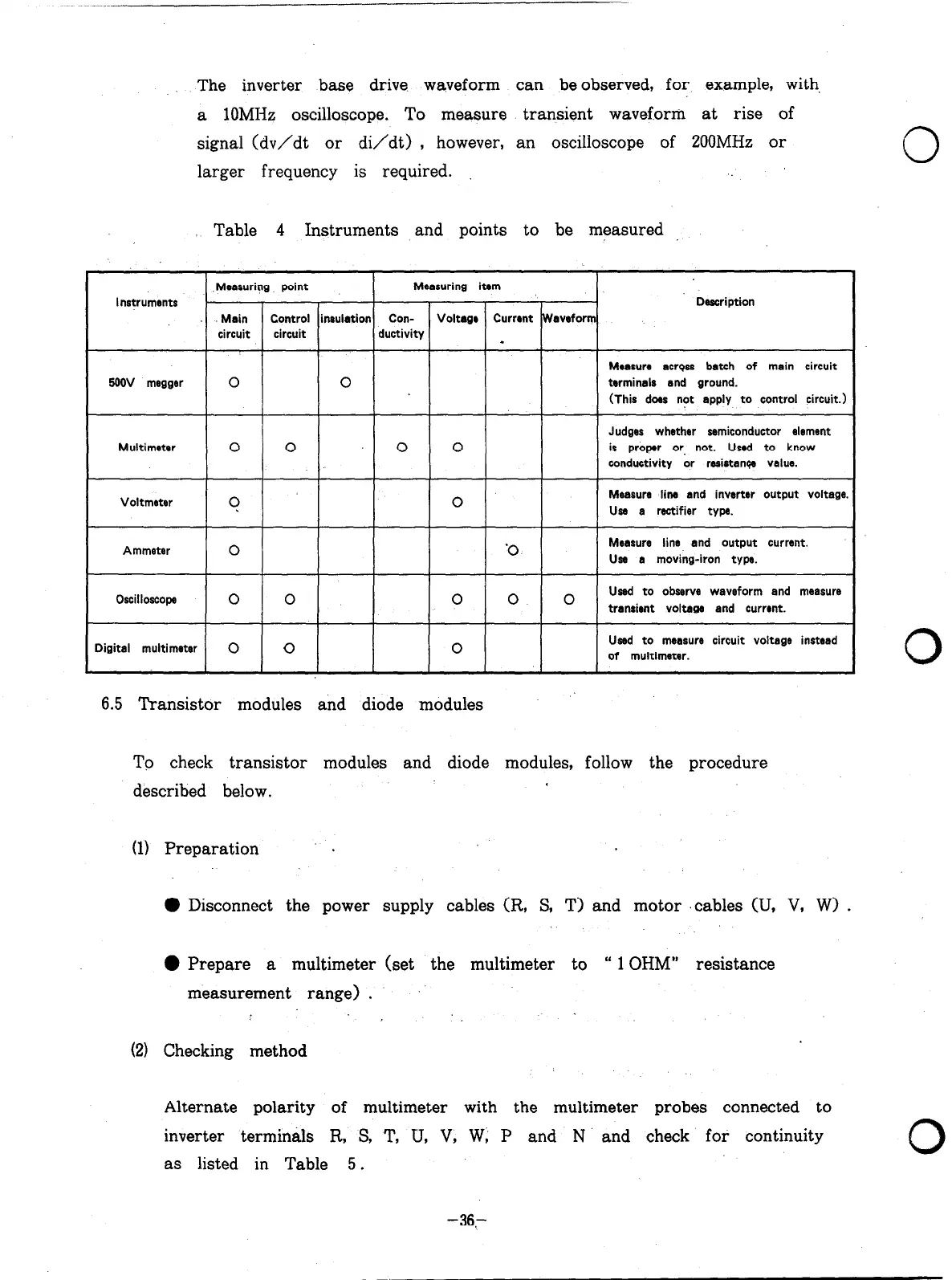
Table 4 Instruments and points to be measured
Measuring point
Measuring item
Instruments
Description
..
Main
Control insulation Con- Voltage Current W aveform
circuit circuit ductivity
5ooV megger
Multimeter
0
0 0
0
t
0 0
Measure across batch of main circuit
terminals and ground.
(This does not apply to control circuit.)
Judges whether semiconductor element
is proper or not. Used to know
conductivity or resistance value.
Voltmster
?
0
Measure line and inverter output voltage.
Use a rectifier type.
Ammeter
0 ‘0
Measure line and output current.
Use a moving-iron type.
Oscilloscope
0
Used to observe waveform and measure
1 ’ 1 ’ 1 ’ 1 transient voltage and current.
Digital multimeter 0
0 0
Used to measure circuit voltage instead
of multimeter.
6.5 Transistor modules and diode modules
To check transistor modules and diode modules, follow the procedure
described below.
(1) Preparation .
0 Disconnect the power supply cables (R, S, T) and motor ‘cables (II, V, W> .
l
Prepare a multimeter (set the multimeter to “ 1 OHM” resistance
measurement range) .
(21 Checking method
Alternate polarity of multimeter with the multimeter probes connected to
inverter terminals R, S, T, U, V, W; P and N and check for continuity
as listed in Table 5.
0
0
0
-36.-
Artisan Technology Group - Quality Instrumentation ... Guaranteed | (888) 88-SOURCE | www.artisantg.com

 Loading...