8 3. CONTROL DEVICES OF PARAMETER UNIT
“ONLY LIGHT FINGER PRESURE IS NECESSARY”
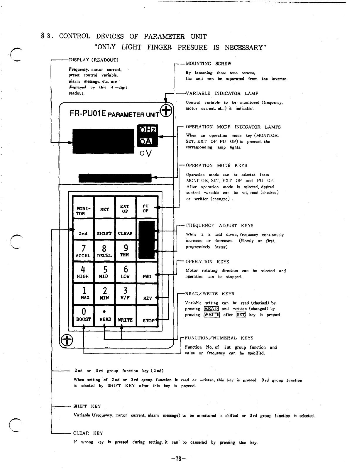
---DISPLAY (READOUT)
7MOUNTING SCREW
Frequency, motor current,
preset control variable,
alarm massage, etc. are
displayed by this 4 -digit
readout.
By loosening these two screws.
the unit can be separated from the inverter.
VARIABLE INDICATOR LAMP
r
i“
Control variable to be monitored
f
_
f%-PUOl E PARAMETER UNli
@
motor current. etc.) is indicated.
OPERATION MODE INDICATOR LAMPS
When an operation mode key (MONITOR,
SET, EXT OP. PU OP) is pressed. the
corresponding lamp lights.
I.
1
OPERATION MODE KEYS
Operation mode can be selected from
MONI’I’OH. WI’, EXT OP and PU OP.
Afler operation mode is selected. desired
control variable can bc set, read (checked)
or written (changed)
I
FliEQUI%‘CY ADJUST KEYS
While it is held down, frequency continously
increases or decreases. (Slowly at first,
progressively faster)
HIGH
r
OPERATION KEYS
Motor rotating direction can be selected and
operation can be stopped.
-READ/WRITE KEYS
I?
. . I
\I I
1-1
I
T I 1
I
\!
I
Variable setting can be read (checked) by
pmssing ml and written (changed) by
pressing [WRITE( after m key is pressed.
.FUNCTION/NUMERAL KEYS
d
I
Function No. of 1 st group function and
1 -
I
value or frequency can be specified.
- 2nd or 3rd group function key (2 nd)
When setting of 2nd or 3 rd qroup function is read or written, this key is pressed. 3 rd group function
is selwted by SHIFT KEY after this key is pressed.
- SHIFT KEY
Variable (frequency, motor current, alarm message) to be monitored is shifted or 3rd group function is selected.
- CLEAR KEY
If wrong key is pressed during setting, it can be cancelled by pressing this key.
-73-
Artisan Technology Group - Quality Instrumentation ... Guaranteed | (888) 88-SOURCE | www.artisantg.com

 Loading...