6.1.2
Overshoot Detection Home Return Positioning
Method
< Overshoot detection home return positioning
method >
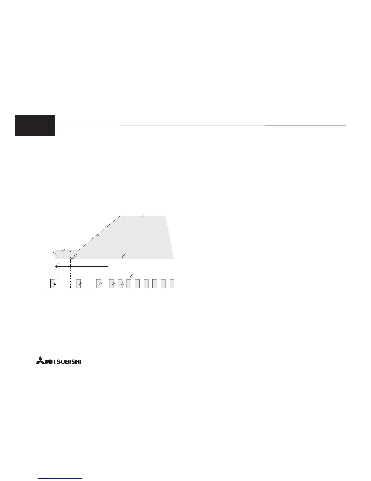
●With this method, the motor starts deceleration when
the dog is in contact with the dog switch, and the motor
is stopped immediately when one (or several) zero
point signal PG0 is received after the dog has passed
the dog switch. (BFM #3 b13 = 1)
➀ With this method, the length L of the dog is required
to be determined so that deceleration is completed
until the dog has passed the dog switch.
➁ Dispersion in the point at which the dog switch
becomes unactuated while the dog is passing the
dog switch is required to be adjusted so that the
dog switch is actuated within the interval between
two PG0 signals at any time.
(The actuation start point is not required to be
adjusted.)
➂ BFM #12 determines how many zero point signals
PG0 should be counted after the dog has passed
the dog switch. With this method, set the BFM #12
always to 1 so that the motor is stopped at the first
zero point signal PG0.
➃ When the operation is stopped, the deviation
counter clear signal CLR of the servo amplifier is
output. The home position (BFMs #14 and #13)
value is transferred to the current position (BFMs
#27 and #26), and the home position return
completed flag (BFM #28 b2) is set to 1.
• It may be required to perform a home return
operation after the dog has passed the dog switch.
In such a case, the dog should be preliminarily
moved back to a position before the dog switch by
the jog operation before the home position return
operation is performed again.
This procedure may be automatically performed
when the limit switches for detecting the forward
and reverse limits are connected to the PC. (See
Section 6.1.4.)
ON
OFF
High speed V
RT
(BFMs #10 and #9)
Number of zero point signals (BFM #12)
Example: 1
Dog passes
the dog switch.
Dog is in contact
with the dog switch.
Zero point
signal PG0
Degree of deceleration
(BFM #15)
Home position
(BFMs #14 and #13)
&
Creep speed V
CR
(BFM #11)
Home position
return direction
(BFM #3 b10, b9)
#
%
$
6
FX-1PG/FX
2N
-1PG PULSE GENERATOR UNIT OUTLINE OF OPERATION MODES
6-3
 Loading...