6.7
Various Operation Modes and Buffer
Memory Setting
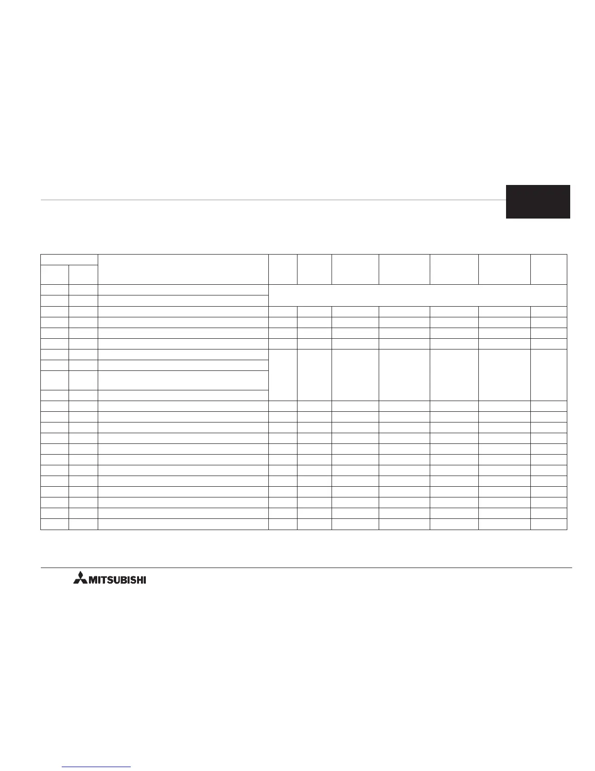
< Various operation modes and buffer memory
setting >
O indicates the item required to be set.
BFM No.
Name JOG
Home
position
return
Single
-speed
positioning
Interrupt
single-speed
positioning
Two
-speed
positioning
External
command
positioning
Variable
speed
Higher
bits
Lower
bits
— #0 Pulse rate
Not required to be set for motor system of units (PLS and Hz).
Required to be set for machine and combined systems of units.
#2 #1 Feedrate
— #3 Parameter O O O O O O O
#5 #4 Maximum speed O O O O O O O
— #6 Bias speed *1 O O O O O O O
#8 #7 JOG speed O — — — — — —
#10 #9 Home position return speed (high speed)
—O — — — — —
— #11 Hime position return speed (creep speed)
— #12
Number of zero point signals for home
position return
#14 #13 Home position
— #15 Acceleration/deceleration time O O O O O O —
— #16 Reserved — — — — — — —
#18 #17 Set position (I) — — O O O — —
#20 #19 Operating position (I) — — O O O *3 *3
#22 #21 Set position (II) — — — — O — —
#24 #23 Operating velocity (II) — — — — O O —
— #25 Operation command O O O O O O O
#27 #26 Current position *2 — *2 *2 *2 — —
— #28 Status information *2 *2 *2 *2 *2 *2 *2
— #29 Error code *2 *2 *2 *2 *2 *2 *2
— #30 Model code *2 *2 *2 *2 *2 *2 *2
— #31 Reserved — — — — — — —
*1 When a servo motor is used, the initial value 0 can be used. *2 Valid information
*3 FP/RP output is generated by a positive/negative speed command. The absolute value shall be a value
within the range between the bias speed (BFM #6) and the maximum speed (BFMs #5 and #4).
6
FX-1PG/FX
2N
-1PG PULSE GENERATOR UNIT OUTLINE OF OPERATION MODES
6-12
 Loading...