3.
TERMINAL ARRANGEMENT
3.1
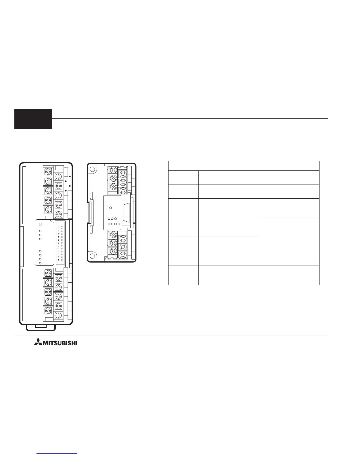
Terminal Arrangement and LED Indication
FX-1PG FX
2N
-1PG
POWER
STOP
DOG
PG0
FP
RP
CLR
ERR
1PG
SG
STOP
S/S
PGO+
DOG
PGO-
VL
FP0
COM0
RP
COM1
VH
VL FP
RP
CLR
CLR
POWER
1PG
STOP
S/S
DOG
COM1
PG0+
FP
VIN
RP
COM0
PG0-
S/S
<LED allocation>
Common between FX-1PG and FX
2N
-1PG
POWER
Indicates power status of PGU.
Lighted when 5 V is supplied from PC.
STOP
Lighted when stop command is entered.
Lighted by either STOP terminal or BFM #25 b1.
DOG
Lighted when DOG input is entered.
PG0
Lighted when zero point signal is entered.
FP
Flashes when forward
pulse or pulses are
output.
Output format can be
modified using BFM #3
b8.
RP
Flashes when reverse
pulse or direction are
output.
CLR
Lighted when CLR signal is output.
ERR
Flashes when error has occurred. Start
command is not accepted when error has
occurred.
3
FX-1PG/FX
2N
-1PG PULSE GENERATOR UNIT TERMINAL ARRANGEMENT
3-1
 Loading...