7.
OUTLINE OF FROM/TO INSTRUCTION (PC)
7.17.1
FROM/TO Instruction
m1 : Special unit/block No. (K0 to K7 starting from the one nearest the basic unit)
m2 : Head address of buffer memory (m2 = K0 to K31)
D• : Head address of transfer destination
T, C, D, KnM, KnY, KnS, V and Z can be specified, and element No. can be coupled
with an index.
n : Number of transfer points
(K1 to K32 for 16-bit instruction, and K1 to K16 for 32-bit instruction)
m1, m2, n : Same as above
S• : Head address of transfer destination
T, C, D, KnX, KnM, KnY, KnS, V, Z, K and H can be specified, and element No. can
be coupled with an index.
●When X010 and X011 are turned off, transfer is not performed, and data in the transfer destination is not changed.
For the details, refer to the programming manual of the PC main unit.
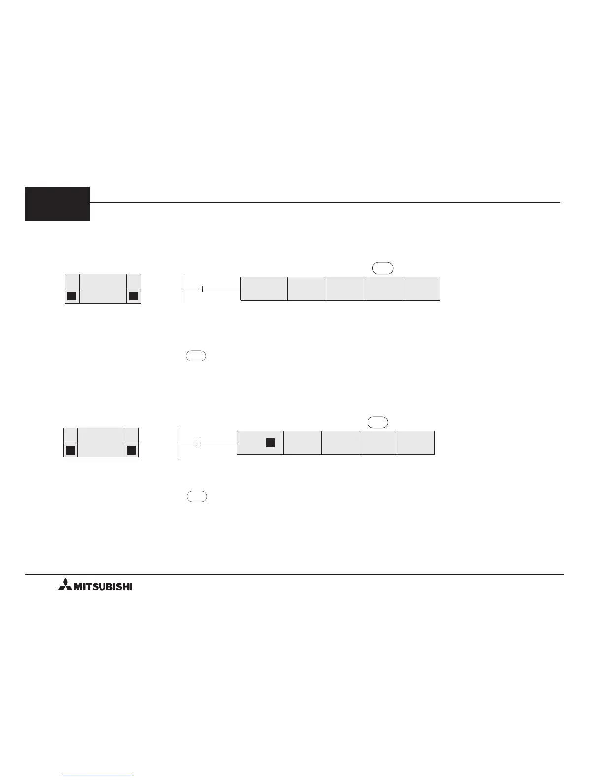
FNC 78
FROM
D P
X010
FROM
K2 K26 D120 K2
Reading
command
m1 m2
D•
n
BFMs #26 and #27 in
special unit No.2 → D120
and D121
Readin
 Loading...