7 - 6
MELSEC-Q
7 MEMORY CONFIGURATION AND DATA PROCESS
7.2 Data transmission process
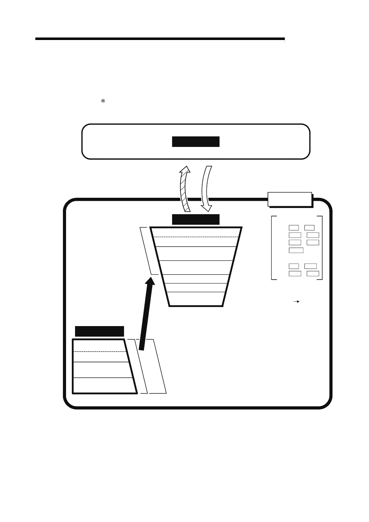
The data is transmitted between the QD75 memories with steps (1) to (8) shown
below.
The data transmission patterns numbered (1) to (8) on the right page correspond to
the numbers (1) to (8) on the left page.
Parameter area (a)
Parameter area (a)
Parameter area (b)
Monitor data area
Control data area
Buffer memory
ROM
Parameter area (a)
Parameter area (b)
(2) TO instruction(4) FROM instruction
QD75
Pr.1
to
Pr.24
to
to
Parameter area (b)
to
Pr.25
to
Pr.150
CPU module
Positioning data area
(No.1 to
600)
Block start data area
(No.7000 to 7004)
PLC CPU
memo area
(1) Power supply ON/
CPU module reset
Flash ROM
Positioning data area
(No.1 to
600)
Block start data area
(No.7000 to 7004)
Pr.7
Pr.11
Pr.43 Pr.57
Pr.8
Pr.10
Pr.42
(3) PLC READY signal
[Y0] OFF ON
 Loading...
