12 - 43
MELSEC-Q
12 CONTROL SUB FUNCTIONS
[3] Setting the speed change function from the CPU module
The following shows the data settings and sequence program example for
changing the control speed of axis 1 from the CPU module. (In this example, the
control speed is changed to "20.00mm/min".)
(1) Set the following data.
(Use the start time chart shown in section (2) below as a reference, and set
using the sequence program shown in section (3).)
Buffer memory address
Setting item
Setting
value
Setting details
Axis
1
Axis
2
Axis
3
Axis
4
Cd.14
New speed value 2000 Set the new speed.
1514
1515
1614
1615
1714
1715
1814
1815
Cd.15
Speed change
request
1 Set "1: Change the speed". 1516 1616 1716 1816
Refer to Section 5.7 "List of control data" for details on the setting details.
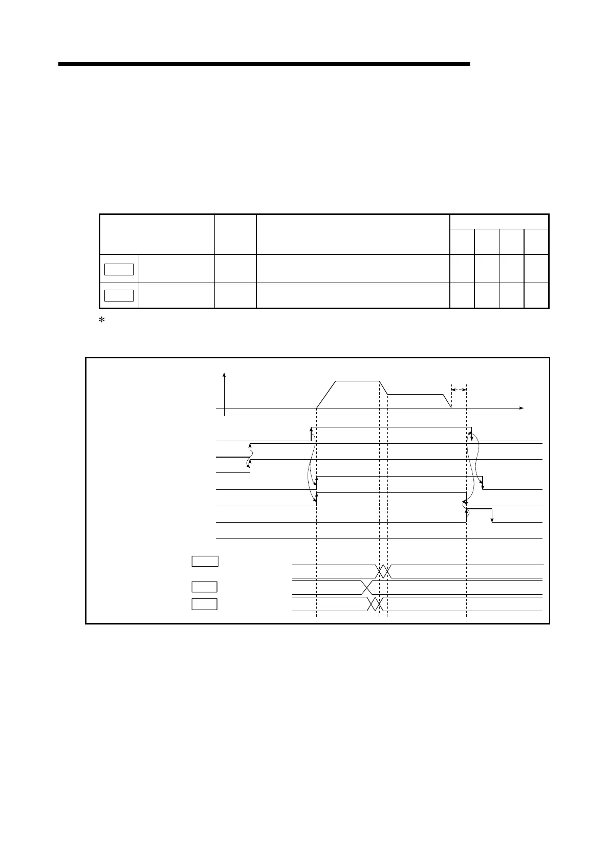
(2) The following shows the speed change time chart.
Cd. 15 Speed change request
Cd. 14 New speed value
In speed change
processing flag
BUSY signal
QD75 READY signal
Error detection signal
V
t
1
0
0
1
0
2000
0
Start complete signal
Dwell time
PLC READY signal
Positionin
start si
nal
Positioning complete signal
[Y10]
[Y0]
[X0]
[X10]
[XC]
[X14]
[X8]
Md. 40
Fig. 12.28 Time chart for changing the speed from the CPU module
 Loading...
