Printed in Japan
Mitutoyo Corporation 1-20-1 Sakado, Takatsu-ku, Kawasaki City, Kanagawa 213-8533
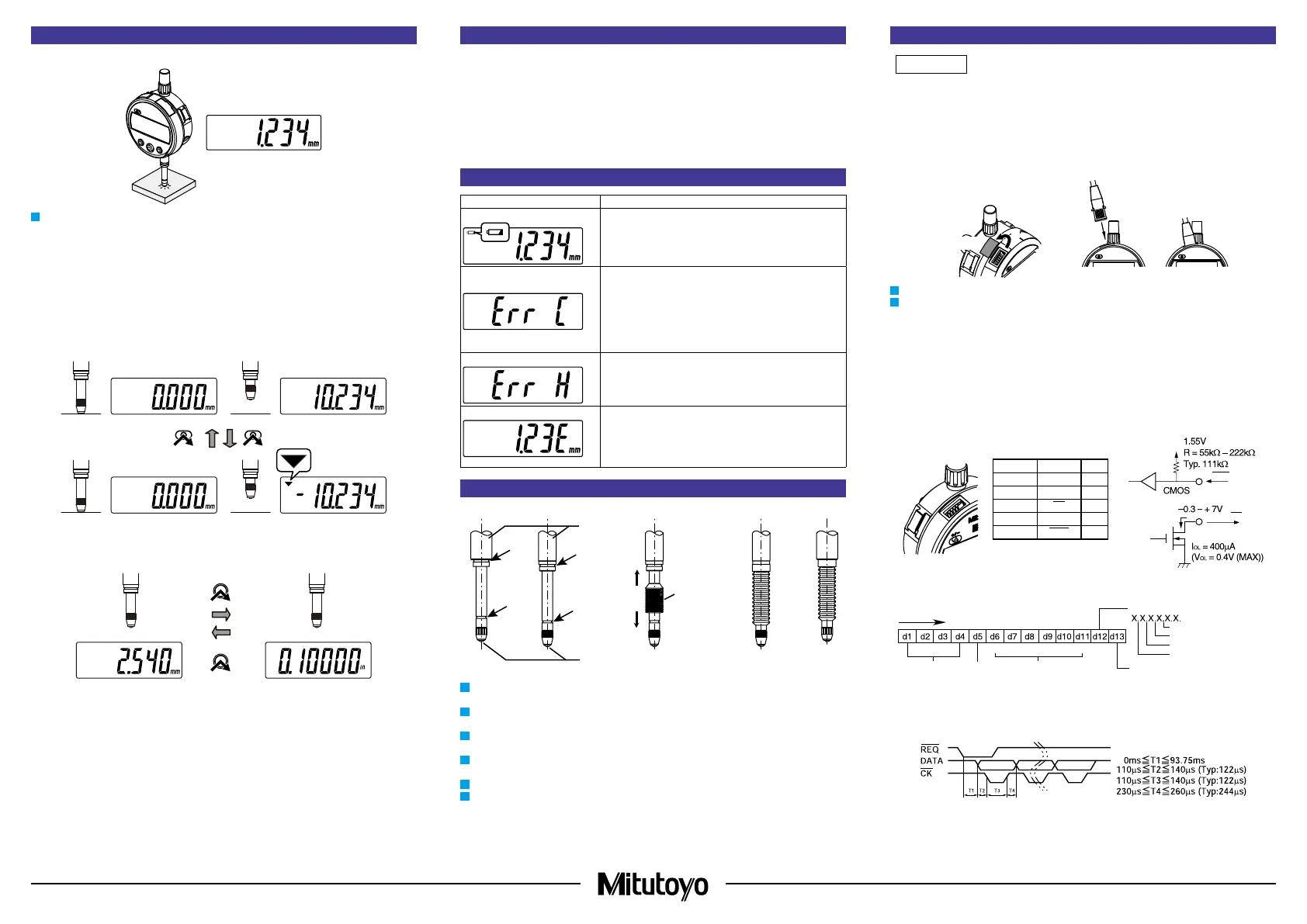
6. Measurement Method
1) Measurement
Workpiece
1
Gradually and lightly place the contact point on the workpiece in the same orientation and
conditions as for reference point setting, and then read the indicated value.
Tips
If the contact point strikes the workpiece to be measured hard, the workpiece may deform and
measurement results may be aected.
2) Switching counting direction
The counting direction can be changed by pressing the [+/-] key. If the product is set to negative
counting when the spindle is pushed in, [▼] is shown on the top left of the display.
+
/
-
+
/
-
3) Switching units
Press the [in/mm] key to switch the unit between in (inches) and mm (millimeters).
in/mm
7. Precautions after Use
• When cleaning, wipe this product with a soft cloth moistened with diluted neutral detergent. Do
not use an organic solvent such as thinner, which may cause the product to deform or
malfunction.
• Dirt on the spindle may lead to malfunction. Clean with a cloth moistened with alcohol, etc. before
use.
• Do not lubricate the spindle with lubricating oil, etc.
• If the product is to be out of use for 3 months or more, remove the battery before storage. Liquid
leakage from the battery may damage the product.
• Do not store the product in a place with a high temperature or humidity, or a lot of dust or oil mist.
8. Errors and Troubleshooting
Error Display Causes and Countermeasures
Battery voltage decrease mark
Battery is depleted. Replace with a new battery.
Sensor contamination detection
error
A sudden change in temperature may create condensation on
the detector, or it may be contaminated by other sources.
Turn the power o and allow the product to adapt to the
temperature for about 2 hours.
If it does not recover after adapting to the temperature, repair is
required: consult with your dealer or agent or with our sales
oce.
Hardware error
This error indicates a hardware abnormality. Repair is
necessary when the error is generated. Please contact our
sales oce.
ABS synthesis error
Although this may occur during high-speed spindle move-
ment, there is no eect on measurement. Use the product as
is. If it occurs while the spindle is not moving, the internal
sensor has failed. In this case, repair is required: consult with
your dealer or agent or with our sales oce.
9. Rubber Boot Replacement (ID-S112PX, ID-112PXB)
Stem
Contact point
Rubber boot
(A)
(B)
(A)
(B)
1
Remove the old rubber boot and wipe away dust or oil from the stem groove (A) and spindle
groove (B) with alcohol, etc.
2
Put the rubber boot on the spindle so that the rubber boot end with the larger bore is on the
stem side, and then set the rubber boot in between the stem and the contact point.
3
Lightly apply a small amount of room temperature curing silicone adhesive to grooves (A) and
(B). At this time, be careful not to apply silicone adhesive to the spindle sliding surface.
4
Pinch the top end of the rubber boot with a tool such as at tip tweezers and t it into stem
groove (A).
5
Attach the bottom end of the rubber boot to spindle groove (B) by pressing manually.
6
Wipe away excess adhesive with a clean cloth.
10. Output Function
For use with a Mitutoyo linear gage counter (EC-101D, EG-101D, EH-102D) connected, set the
linear gage counter "SDP input WAIT setting" to "No WAIT" before use. If used with other
settings, an error will be displayed on the linear gage counter.
1) Externally outputting the displayed value
The displayed value can be output to a device supporting Digimatic output format by connecting
the product and the external device with a connection cable (option). The product can be
connected to an optional external display, external printer, PC, etc.
1
2
Cap
Connection cable
1
Press the [ON/OFF] key to turn o the product.
2
Connect the product and the external device.
1. Remove the cap of the output connector of the product.
2. Connect the product and the external device with a connection cable.
Tips
• 2 types of connection cables (options), No. 905338 (1 m) and No. 905409 (2 m), are available
for this product.
• When connecting a connection cable, pay attention to the connector direction as you insert it.
• Store the removed cap to prevent loss.
• Always install the cap if a connection cable is not used.
2) Output connector
Pin No. Signal I/O
(1) GND -
(2) DATA O
(3)
CK O
(4) - -
(5) REQ I
• Input
• Output
REQ
DATA, CK
(1)
(5)
3) Output data format
(1) Output order
(2) All "F"
(3) Sign
(4) Measured
value
(5) Decimal
point
(6) Unit
4) Timing chart
3 (1100)
(1)
MSD LSD
(2)(4)
(3)
+: 0 (0000)
(6)
mm: 0 (0000)
● Positive count
● Negative count

 Loading...