Chapter Two: Installation Connectors
27
Connectors
Note
Overall metal braided shielded cables, properly grounded at both ends,
are required to meet CE specifications.
15-Pin Type “D” Connector
The 15-pin Type “D” connector, located at the end of the 6” pigtail cable, is used to connect the
253 valve to a controller. The system interface cables are listed in Table 5, page 20.
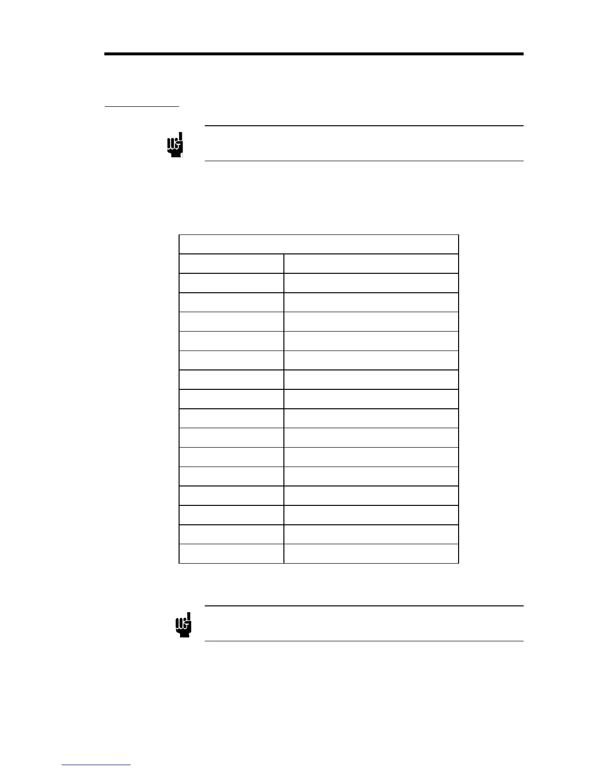
15-Pin Type “D” Connector Pinout
Pin Assignment
1 No Connection
2 No Connection
3 Limit Switch Common
4 Open Limit Switch
5 Close Limit Switch
6 No Connection
7 No Connection
8 Winding A
9 Winding A'
10 Winding A Common
11 No Connection
12 No Connection
13 Winding B
14 Winding B'
15 Winding B Common
Table 6: 15-Pin Type “D” Connector Pinout
Note
The “No Connection” pin assignment refers to a pin with no internal
connection.
 Loading...


