Chapter Four: Operation How To Ad
ust the Tri
Point Values
37
How To Adjust the Trip Point Values
Equipment required:
digital volt meter (DVM)
3
/
16
” hex or open-ended wrench
Caution
Only qualified individuals should perform the adjustments. You
must comply with all the necessary ESD and handling precautions
while adjusting the instrument. Proper handling is essential when
working with all highly sensitive precision electronic instruments.
Each trip point has a test jack that allows you to measure the trip point setting. The test jacks are
located inside the unit. Figure 14, page 39, shows the location of the test jacks and a ground
connection. The trip point adjustment pots, located on the top of the unit, allow you to vary the
trip point setting.
The range of the trip point setting is 0 to 5 Volts, corresponding to 0 to 100% of pressure
transducer full scale.
Note
The tri
oint ran
e is from 0 to 5 Volts, re
ardless of the ran
e of the set
point input and pressure output signals.
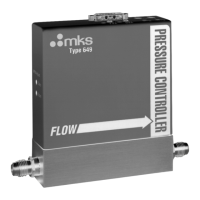
1. Stop the gas flow through the 649 controller.
2. Remove any leads or wires attached to the connector on the 649 controller.
3. Use a
3
/
16
” hex wrench (or open-ended wrench) to remove the hex nuts on each side of
the I/O connector.
Refer to Figure 6, page 21, for the location of the hex nuts on the I/O connector. Place
the hex nuts aside for safe keeping.
4. Position the controller with the front side facing you, and pull up on the enclosure to
remove it.
The board assembly will be visible, with the Transducer board facing you and the
Control board behind it.
5. Insert the positive test probe into the test jack labeled “TP A” and the ground probe into
the test jack labeled “Gnd.”
Insert the probes sufficiently to obtain a good reading. There is no back plane in the test
jacks to stop the probe.
6. Use a small screwdriver to adjust the trip point adjustment pot labeled “TP A”.


 To Next Page