12. Auto-Aligner
For the closest match of virtual graphics to real world camera the StarTracker oers through-
lens calibration to tweak osets that were set during the mapping and calibration processes.
You will need to have the ST sensor unit rigidly mounted on the studio camera, have performed
the mapping and O,X,Y map alignment and ST sensor calibration steps.
12.1 Auto-Aligner Operation
Before commencing with the Auto-Aligner makes sure you have measured and entered your TP
Right, TP Down and TP Forward accurately (see camera osets).
The Auto-Alignment process will involve marking 3 known reference points in the studio and
gathering several observations of them by looking at them through the centre of the studio
camera lens. From this the system will automatically tweak the map and camera osets to try to
give tracking data that best matches these viewpoints.
Note: This calibration process cannot tweak the “TP Forward” or “Roll Oset” values,
as set in the Osets menu.
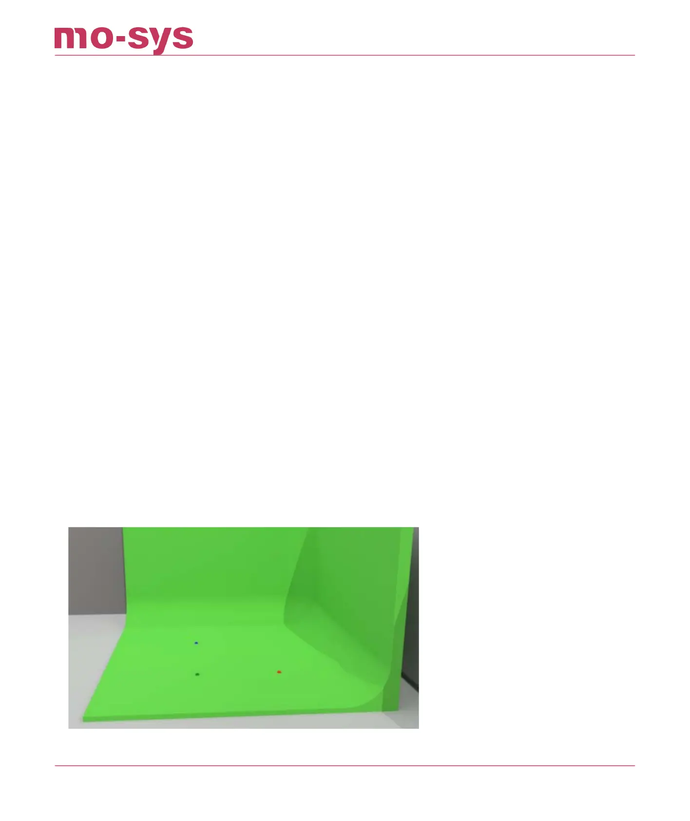
To start, measure and mark 3 points on the studio oor whose 3D positions relative to the map
origin (0 position) you can measure accurately in X, Y and H (height). In the below image the red
marker is our zero point. Ideally the marked points should be in an area of the studio where the
talent will be later and where the cameras are mostly looking at.
If you have an Auto-Align kit, assemble it accordingly.
If you have an LED volume with oor tiles you can use the tiles as reference. See image below:
StarTracker Max Manual
2023 - 2024 © Mo-Sys Engineering Ltd. All rights reserved 49 of 70