Mobileye Proprietary and Confidential
support@mobileye.com
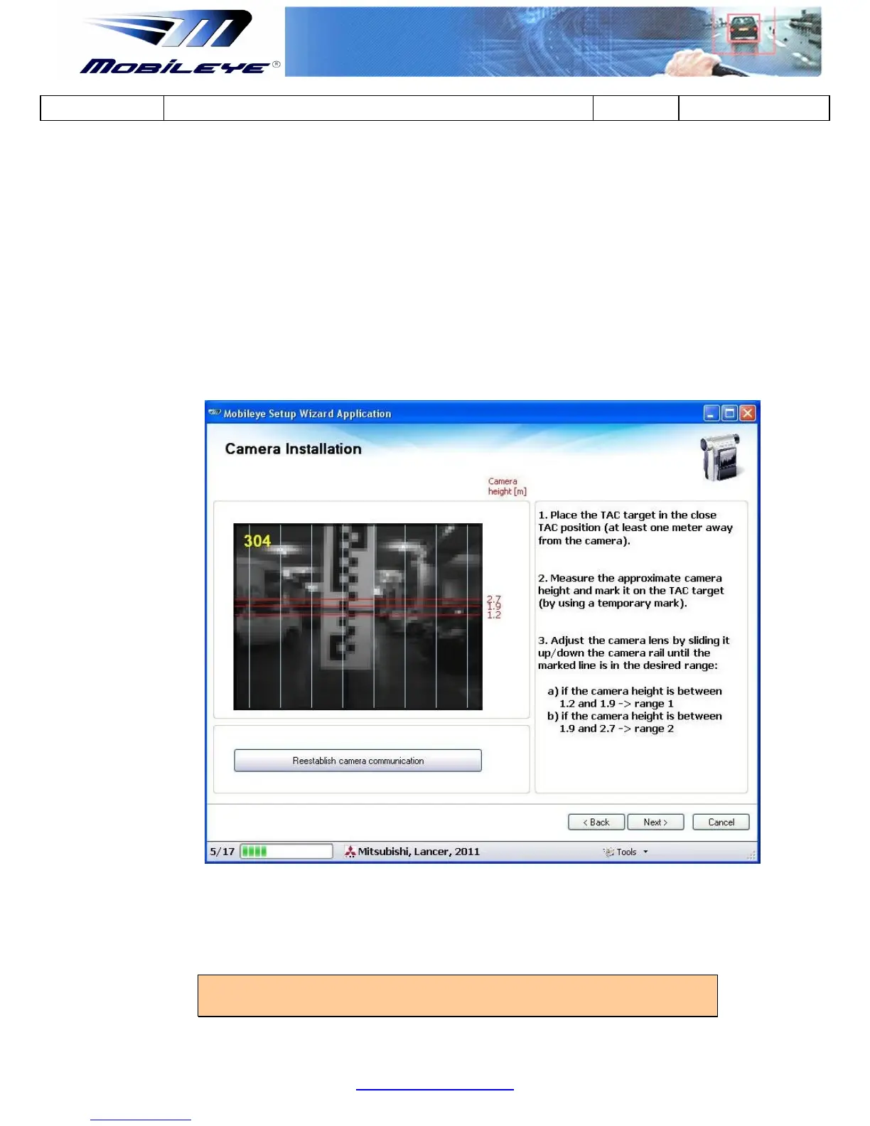
3. After marking the Camera Height on the TAC Target use the image feed
(camera installation slide) to adjust the Camera Lens Angle by sliding it Up/Down
the Camera Railing until the Marked Line is in the Desired Camera Height Range.
a) If the Camera Height is between 1.2m and 1.9m place the Marked Line
between the 2 bottom red lines (indicated by “1.2” and “1.9”) on the right hand
of the image feed = Zone 1
b) If the Camera Height is between 1.9m and 2.7m place the Marked Line
between the 2 upper red lines (indicated by “1.9” and “2.7”) on the right hand of
the image feed = Zone 2
4. Once the Camera Height is Adjustment to the correct Zone, Lock (tightened) the
Camera Adjustment Screw and press next to continue.
NOTE: Do not re-connect the Main Unit Back Covers until the Calibration
Process is completed.