74/152
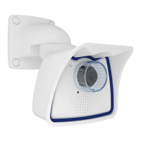
Q25 Camera Manual: Installation
© MOBOTIX AG • Security-Vision-Systems • Made in Germany
www.mobotix.com • sales@mobotix.com
2.2.2 Procedure
1. Install and prepare the network connection.
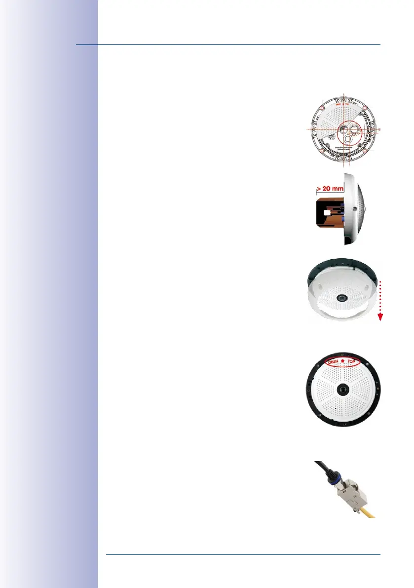
2. Install the flush-mounted wall outlet: The pre-installed
cable attached to the camera must be connected with
the on-site network cable. For installation without acces
-
sories, a flush-mounted wall outlet must be installed first,
in order to provide a connection. The cabling is perfectly
protected and cannot be seen or damaged. The camera
cannot be mounted directly on top of protruding wall
outlets. Use the supplied camera drilling template (fold-out
at the end of this manual) to mark the position of the wall
outlet for the desired camera position.
3. Remove the outer shell: Remove all four Allen screws
using the supplied Allen wrench and lift o the outer
shell.
4. Drill the holes: Drill the holes for the supplied screw
anchors (see drilling template). Remember to take the
proper direction of the camera into consideration (OBEN
/ TOP arrow pointing upwards for wall installation, or in
the direction of the longer wall for ceiling installation in
rectangular rooms).
5. Connect the cable: Connect the on-site network cable
to the camera patch cable using a standard connector.
RJ45 patch cable: 50 cm
(19.7 in) cable incl., other
lengths available from
MOBOTIX as accessories
Due to the space
required for cable and
connectors, we recom-
mend a ush-mounted
wall outlet with an
installation depth of
at least 20 mm/8 in