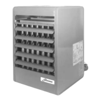
Do you have a question about the Modine Manufacturing PD and is the answer not in the manual?
| Brand | Modine Manufacturing |
|---|---|
| Model | PD |
| Category | Gas Heater |
| Language | English |
Covers risks from improper installation, corrosive vapors, and flammable liquids.
Actions to take if a gas leak is detected and general safety advice.
Guidance for qualified personnel and steps for unit inspection upon arrival.
Explains DANGER, WARNING, CAUTION, and IMPORTANT designations.
Covers venting, electrical connections, wiring, gas pressure, and voltage requirements.
Addresses risks like corrosive vapors, improper ducting, and wet controllers.
Guidance on selecting a safe and suitable location for unit installation.
Specifies minimum distances to combustible materials for safe unit placement.
Details requirements for providing adequate combustion air to the unit.
Guidelines for minimizing noise and vibration transmission from the unit.
Instructions for safely lifting and handling the unit during installation.
Detailed steps for securely suspending the unit using threaded rods or pipe adapters.
Instructions for installing vents according to codes and specific site conditions.
Critical warnings about operating unvented, blocked vents, and using approved exhausters.
Specifies requirements based on appliance category (I, II, III, IV).
Table provides minimum vent height from roof based on roof pitch.
Provides requirements for condensate drainage and vent system cleaning.
Guidelines for connecting to existing chimneys or common vents for Category III/IV units.
Warnings about leak testing, gas pressure limits, and purging procedures.
Guidelines for installing gas piping, including code compliance and pipe sizing.
Details on installing a sediment trap and manual shut-off valve for safety.
Warnings about disconnecting power, correct wiring, wire ratings, and voltage.
Instructions for wiring installation, grounding, and component connections.
Details on voltage, phase balance, protection, and external service connections.
Practices for uniform air distribution, access panels, and blower enclosure kits.
How to adjust blower speed based on airflow and external static pressure.
Important note: Do not attach ductwork of any kind to propeller models.
Steps for installing and connecting the blower assembly and motor.
Procedure for adjusting motor sheave for proper blower speed and performance.
Ensuring correct belt tension and sheave alignment for optimal blower operation.
Ensuring proper power, wiring, venting, and mechanical checks before initial startup.
Verifying electrical operation, blower rotation, motor performance, and gas supply.
Procedure for adjusting the pilot flame for proper ignition and operation.
Steps to adjust manifold pressure for proper gas input to the burners.
Procedure for adjusting primary air for optimal flame on natural gas.
Procedure for adjusting air shutters and manifold for optimal flame on propane.
Describes operation for single-stage and two-stage standing pilot controls.
Describes operation for single-stage and two-stage intermittent pilot controls.
Details operation for two-stage standing and intermittent pilot systems.
Explains operation of mechanical modulating gas controls with automatic pilot ignition.
Description of single-stage, two-stage, and modulating gas valves and ignition controllers.
Details on the time delay relay and low voltage terminal board for wiring connections.
Describes step-down transformers, high limit switches, and blocked vent safety switches.
Covers vent pipe connections and optional blower motor configurations.
Detailed performance data for blower models under various conditions.
Information on motor specifications and power requirements for blower units.
Performance data when using external filters with blower units.
Important considerations for ordering 575V units and related transformers.
Details on 40° downward, 90° vertical, 40° splitter, and 5-way nozzles.
Data on mounting height, heat throw, and heat spread for various nozzle types.
Performance data for 30° downward deflector hoods for propeller units.
Performance data for 60° downward deflector hoods for propeller units.
Performance data for 90° downward deflector hoods for propeller units.
Performance data for 30° downward deflector hoods on blower units.
Performance data for 60° downward deflector hoods on blower units.
Performance data for 90° downward deflector hoods on blower units.
Table of dimensions for PD models, including overall size and connection points.
Specifics on mounting hole sizes and gas connection sizes for PD units.
Table of dimensions for BD models, including overall size and connection points.
Specifics on mounting holes, blower enclosure, and gas connections for BD units.
Routine checks for dust, dirt, heat exchanger condition, wiring, and gas controls.
Step-by-step instructions for removing manifold and burner/pilot assemblies.
Flowchart to diagnose and resolve issues related to the Blocked Vent Safety Switch.
Explanations of spillage determination and indications of negative space pressure.
Troubleshooting causes and remedies for pilot or main burner ignition failure.
Addresses issues like lifting flames, yellow tipping, and wavering flames.
Troubleshooting flashback, floating flames, flame rollout, and heat output problems.
Explanation of the high limit switch function and troubleshooting when it trips.
Explanation of designations for serial numbers and model numbers.
Details found on the unit's serial plate, including specifications and approvals.
Seller's warranty limitations and exclusions for material and workmanship.
Details warranty periods for heat exchangers, burners, and other components.
 Loading...