Do you have a question about the Moog DigiPack III J141-215 and is the answer not in the manual?
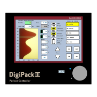
Provides a general overview of the DigiPack III controller and its core functions.
A checklist to ensure all mechanical and electrical installation steps are completed.
Procedures for adjusting the die gap tooling assembly for optimal performance.
Detailed instructions for wiring terminal blocks TB-1 and TB-2.
Explanation of the input/output circuitry for terminal block TB-2.
General steps and requirements for setting up the tooling system.
How to configure machine-specific settings for the tooling system.
Explains parison control principles and machine types.
Details the human-machine interface for controlling the system.
Descriptions of various screens available in the edit area.
Technical details of communication protocols used by the system.
Procedures and objectives for setting up the system for operation.
Details parison control specifics for accumulator machines.
Details on setting and adjusting parison profile points and thickness.
Accessing and configuring machine setup parameters and tooling settings.
Setting up machine-specific parameters and modes for operation.
Procedure for calibrating the die gap tooling for accurate parison control.
| Brand | Moog |
|---|---|
| Model | DigiPack III J141-215 |
| Category | Controller |
| Language | English |