Do you have a question about the Moog IMI220-145D001 and is the answer not in the manual?
Provides a general overview of the system installation process and considerations.
Details the process of installing hydraulic components and related plumbing.
Explains the importance and process of hydraulic system filtration for optimal performance.
Describes the use and function of manifolds for mounting servo-valves.
Introduces servo-actuators as integrated components for cylinders, transducers, and servo-valves.
Outlines the procedure for flushing the hydraulic system before or after component installation.
Discusses common pump failures and offers advice on maintaining servo-valve life.
Covers the installation of DCDT and linear position transducers for monitoring cylinder positions.
Provides detailed instructions and precautions for mounting DCDT position transducers.
Explains mounting precautions for linear position transducers used in specific applications.
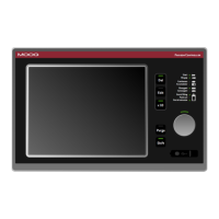
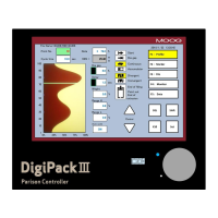
Describes the front panel of the Parison Controller, including touch screen and buttons.
Details the functions of the fast access keys and the entry knob on the control panel.
Explains the use of the USB device for saving or loading recipes.
Describes the meaning and function of each LED indicator on the display panel.
Outlines the general description of pages, including color assignments, header, and footer elements.
Explains how to change numeric, boolean, and alphanumeric setpoints using the control interface.
Details the appearance and structure of the Parison field, including its panels and editing functions.
Describes alternative ways to use vertical arrows and the knob for profile navigation and editing.
Explains the functionality of various function keys for profile manipulation and marker setting.
Covers essential functions like safe conditions, language, and system elements.
Explains how the controller is configured for different machine types.
Illustrates configurations for continuous extrusion and time accumulator modes.
Illustrates configurations for position accumulator mode.
Specifies the close loop sampling time for the controller.
Describes the rear view of the Parison Controller rack and its slot configurations.
Lists the pin assignments and descriptions for the digital input card.
Lists the pin assignments and descriptions for the digital output card.
Lists the pin assignments and descriptions for the analog input card.
Lists the pin assignments and descriptions for the analog output card.
Provides wiring examples for different types of parison controls and actuators.
Provides dimensions and measurement details for the controller's terminal.
Describes the main menu interface and how to access its submenus.
Explains how to set and manage passwords for different access levels.
Details how to change the system date and time format.
Lists the functions associated with the keys in the Main Menu.
Describes the second part of the main menu and its access methods.
Explains how to configure the machine based on its typology.
Allows selection of machine types like continuous extrusion or accumulator.
Covers general machine setup parameters like number of heads, extruders, and points.
Provides guidance on selecting the correct number of points for a parison profile.
Details various machine settings for extrusion, parison, and control functions.
Explains how to select command output types (Voltage or Current) and ranges.
Lists the available language options for the operator interface.
Lists function keys for navigating setup pages.
Presents the second page of machine setup options and configurations.
Covers the setup and display of parison profiles for individual work heads.
Explains how to edit parison profiles and parameters for die opening.
Details parameters like point, value, base, range, and increment for profile editing.
Describes cycle time, weight, shift, feedback, and marker parameters.
Explains the die gap position setting for accumulator or continuous extrusion.
Describes how to add additional weight to single heads with unique profiles.
Explains different interpolation types (Bezier, Linear, Flat, Parabolic) for profile creation.
Details how synchronisms are defined and represented on the profile edit field.
Explains how to dedicate channels for Partial Wall Thickness System (PWDS) control.
Covers head setup procedures, including wiring checks and calibration.
Provides steps to verify correct wiring and calibrate the system.
Details calibration procedures for open loop, closed loop, manual, and automatic modes.
Explains how to select the die type and mobile part for actuator configuration.
Covers parameters like correction enable, time control, purge, and auto run.
Discusses parameters for PID control, dead bands, and output slopes.
Describes the setup page for channels managing the PWDS function.
Presents the second head setup page for accumulator position control.
Details parameters for controlling parison length based on photocell signals.
Explains how correction types (Maximum, Nothing) are applied based on error values.
Describes the accumulator page in accumulator position mode for setting stroke and speed control.
Explains the profile editor for accumulator mode, including rulers and bar graphs.
Details profile parameters like point, value, base, and range for accumulator control.
Covers parameters for accumulator planning, setting, and priority.
Shows the real accumulator position and related popup window information.
Details the accumulator setup page for configuring extrusion control and empty calibration.
Explains how to externally manage the accumulator without profile speed control.
Covers parameters related to time control extrusion, start correction, and filling/extrusion settings.
Describes the work extruder pages, including association and drive command types.
Explains extruder command settings, velocity control, and error correction.
Covers the setup for analog extruders, including type, input, and output calibration.
Explains how to select the extruder type and associated heads.
Details the process of calibrating voltage input for extruder speed.
Explains voltage output calibration for maximum velocity.
Covers minimum and maximum velocity setpoints and ramp slopes.
Discusses extruder speed correction based on errors and algorithms.
Details the setup for digital extruders, including type and duration settings.
Explains the timer switch page for managing temperature control intervals.
Provides an overview of the Input/Output menu for viewing system states and I/O monitoring.
Lists and describes each digital input and its corresponding function.
Lists and describes each digital output and its function.
Lists and describes each analog input and its value.
Lists and describes each analog output and its setpoint.
Explains the production page for setting production targets and monitoring progress.
Details parameters for pieces to be produced, cavities, and cycle times.
Describes the edit page for creating new parison profiles and copying existing ones.
Explains how to copy a visualized profile to a suitable profile slot.
Shows which profiles are assigned to each head and their active status.
Details the recipe page for managing, saving, loading, and formatting recipes.
Explains how to manage recipes, including selecting type, name, and device.
Displays an index of saved recipes with their name, type, dimension, and update time.
Describes the process of copying recipes between RAM and USB storage.
Allows viewing additional information related to saved recipes.
Explains the alarms page for displaying and managing system alarms.
Defines alarm parameters like colors, codes, activation times, and event descriptions.
Provides a comprehensive list of all possible alarms and their triggers.
Describes how to save the current page to a file on USB.
| Brand | Moog |
|---|---|
| Model | IMI220-145D001 |
| Category | Controller |
| Language | English |