PARISON CONTROLLER
moog
Moog Italiana srl - Bergamo MAN145-UM-D01A-EN 5
Moog servo-valves used in blow moulding Parison control are most often internally piloted devices. This means
that the manifolds used will have 4 ports that connect to the machine’s hydraulic system:
“P” port is the incoming high-pressure supply to the valve.
“T” or “R” port is the servo-valve return to tank.
“A” or “C1” port is one of the controlled ports. This should plumb to one end of the programming cylinder.
“B” or “C2” port is the other controlled port. This should plumb to the other end of the programming cylinder.
Some manifolds may be supplied with an additional fifth port labeled “X”. These manifolds are designed for use
with hydraulic systems capable of supplying an independent source of pilot pressure. If the need for this port is
uncertain, contact Moog Field Engineering for additional information.
There is no specification as to which controlled port should plumb to which end of the programming cylinder. The
following suggestions are offered concerning plumbing:
Try to keep the overall length of the controlled port lines as close to equal as possible.
Keep the servo-valve manifold as close to the programming cylinders as possible. The shorter the length
of the control lines, the more accurate position control will be.
Try to plumb all the valves the same way. (All “A” ports to the top of the cylinders or all “B” ports to the top
of the cylinders.) This will reduce confusion and make wiring easier later.
It is EXTREMELY IMPORTANT that plumbing between the controlled ports of the manifolds and the programming
cylinders be completed with solid tube or pipe. Do Not Use Hoses To Make These Connections! Hydraulic supply
up to the filter and the return lines from the servo-valve manifolds can be done with hose if desired.
In a great number of cases, the solid hydraulic lines that connect the controlled ports to the programming cylinders
will provide enough support for the servo-valve and manifold combination. If the machine is prone to excessive
vibration it would be wise to fabricate some type of bracket to support the servo-valve assembly.
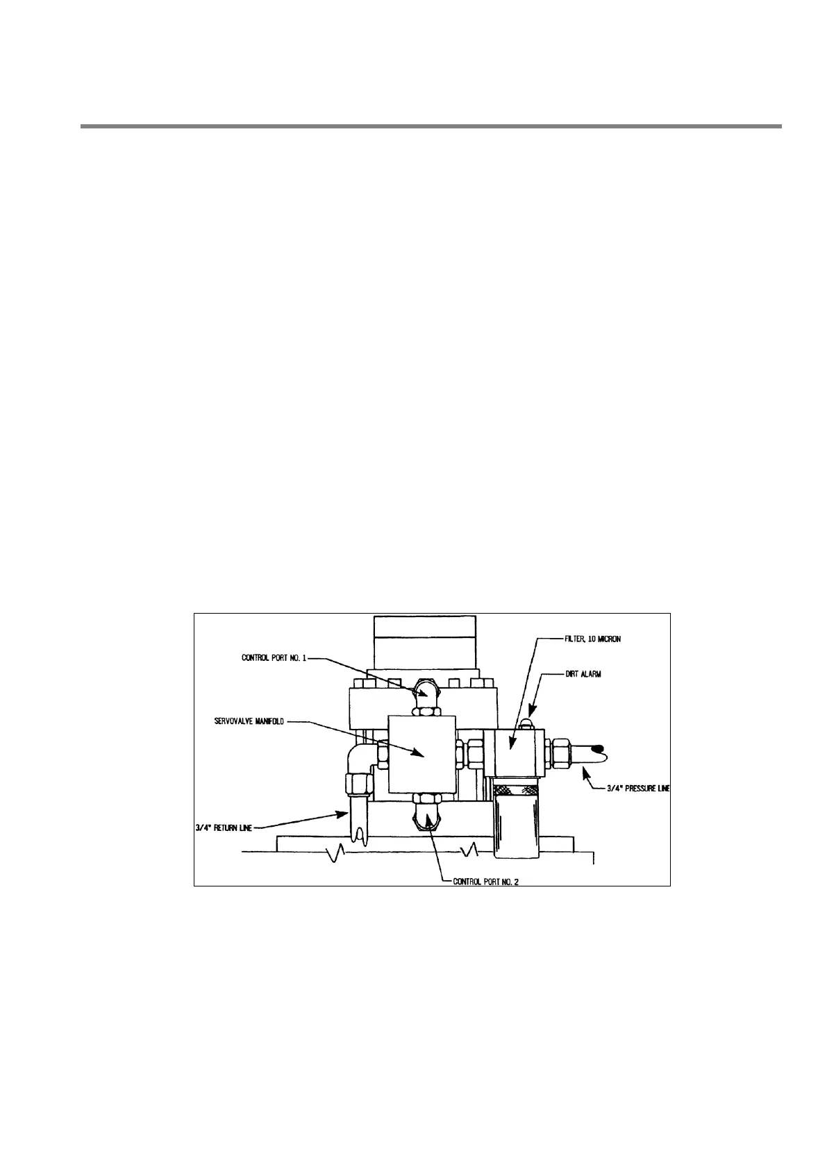
A typical servo-valve and manifold installation is depicted below:
Figure 1
 Loading...