PARISON CONTROLLER
moog
Moog Italiana srl - Bergamo MAN145-UM-D01A-EN 9
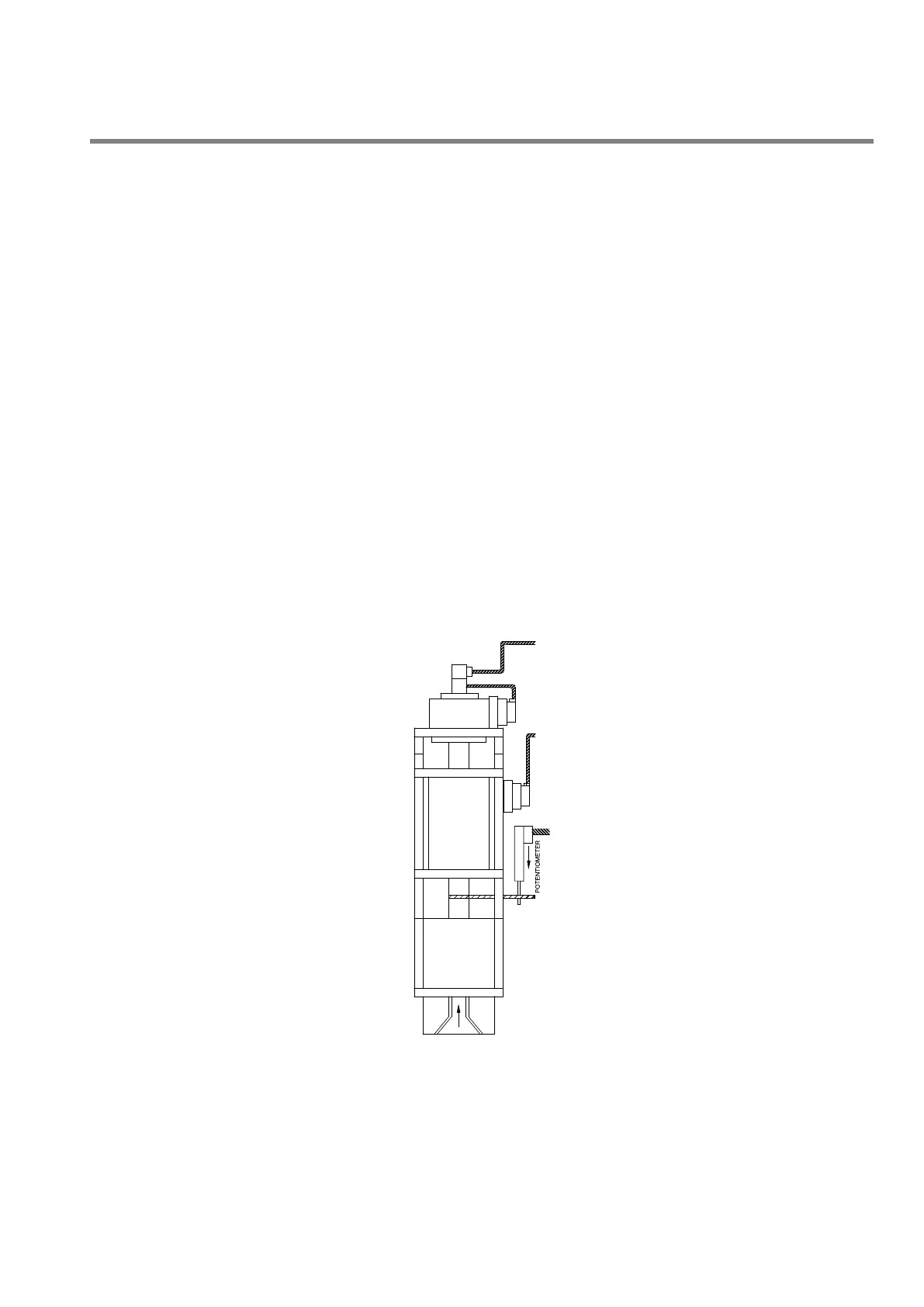
1.10 Linear Position Transducer (position based applications ONLY).
Since the profile is synchronized to the position of the push out ram, the Parison Controller requires a means to
track the ram throughout the push-out stroke. In addition, to keep the profile points properly positioned on the
Parison, the Parison Controller must have control over the accumulator or reciprocating screw’s FULL (End of Fill.)
and EMPTY (End of Extr.) points. Both of these tasks are accomplished by the signal provided from the linear
position transducer, also referred to as a linear pot.
The transducer can be mounted so that the shaft EXTENDS FROM the pot body during push-out, or RETRACTS
INTO the body during push-out, whichever makes for a more convenient mounting method.
As with DCDT’s, there are several precautions that should be observed when mounting linear position transducers:
The pot body and shaft must be as parallel to the push out ram as possible. This will prevent side loading
of the transducer shaft and premature failure of the bushings in the transducer body.
The transducer should never be at the full mechanical end of its stroke in either direction. When mounting
be sure that the shaft is at least 0.25” (~5 mm) from its mechanical end stop when the push out cylinder is
at full bottom (empty).
The body should be rigidly mounted to eliminate the possibility of movement caused by machine vibration.
There should be no more than 1/16 inch (~1.5 mm) of end play in the transducer shaft in the direction of
ram movement when the shaft is secured to the ram follower assembly.
The end of the shaft should never be screwed down tightly to the follower assembly. Instead, the ball joint
on the shaft should be allowed to “float” slightly up and down the securing screw. This will reduce any
stresses caused by the slight misalignment between transducer and cylinder that are always present.
Figure 4
 Loading...