PARISON CONTROLLER
moog
Moog Italiana srl - Bergamo MAN145-UM-D01A-EN 13
2.2 General page description.
2.2.1 Colours assignment for all pages:
The fields that can be reached by cursor and can be changed.
The fields that can’t be reached by cursor and can’t be changed.
Show the value of an analog output.
Show actual value (feedback e.t.a.).
The texts on the screens.
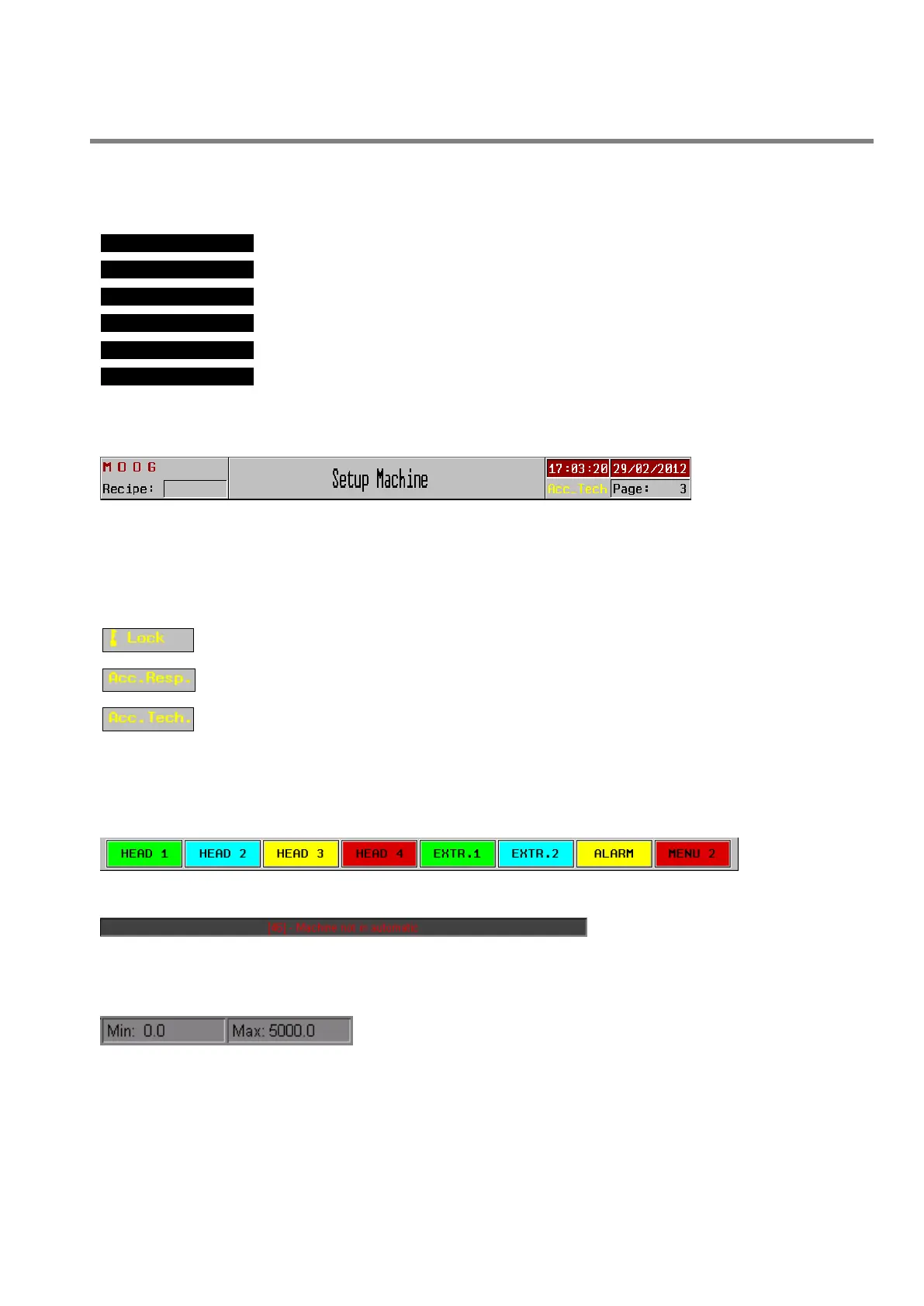
2.2.2 Page Header:
Text left bottom: Shows
the actual recipe that is
working.
Center: Shows the page title.
Date and time of day: Show the actual day, date and hour of the system. For adjustment go to the Technical level
or a Resp. level password.
Text right bottom: (yellow) Shows the current level state:
Lock: No password inserted.
Acc. Resp: Access Responsible Level on. For changing this password enter in Technical
Level and enter in setup machine.
Acc. Tech: Access Technical Level on. This password is fixed by Moog.
The other one shows the current number page.
2.2.3 Page Bottom:
Bottom page: soft
key to change the
page
Alarm line: If there are one or more
alarms on the alarms page, the alarms
are displayed at the bottom of each
page.
This line shows the last alarm and changes the back colour depending on the priority. On the left of the text the
number shows the code of the alarm displayed at the moment.
Min and Max: Minimum and maximum are displayed in the status line.
In the example on the left the minimum valid value is 0, while the
maximum is 5000.
 Loading...