PARISON CONTROLLER
moog
Moog Italiana srl - Bergamo MAN145-UM-D01A-EN 59
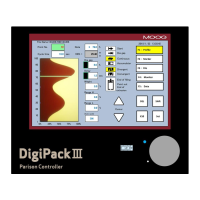
Profile associate: (Only if Free profiles assignment is
enabled) Profile number associated to the head.
Point: Shows in yellow the actual point during the movement
in accordance with the red bar graph on the right side of the
screen. In green the position of the cursor in the Parison field.
Value can be changed from 1 to 400 to set the cursor position.
Value: Shows in yellow the desired percentage setting and in green the value of the point where the cursor is in
the Parison field. By changing this value (0 to 100% max) it is possible to add a new setpoint or modify the existing
one at the cursor position.
Base: Displays the minimum profile value. By changing the base it is possible to shift the whole profile. Range: 0%
to Max limit (Profile). The max limit added to the range must be less or equal to 100% (base + range <= 100).
Range: Displays the profile range as difference between maximum and minimum value. By changing the range it
is possible to resize the entire profile. Range: 1% to Max limit ( Weight). The max limit added to the base must be
inferior or equal to 100% (base + range <= 100).
Increment: This is the amount by which the setpoint value is incremented or decremented when editing the profile
at the cursor position.
Vertical arrows: Shows the vertical arrows active function (chapter 2.5.4).
Knob: Shows the entry knob active function (chapter 2.5.4).
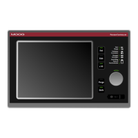
4.5.3 Cycle parameters.
Cycle time: Displays in yellow the Parison
cycle time during the movement and in green
the Parison cycle time in seconds.
Weight: Change the weight of the profile.
Shift: It is possible to indicate by how many
points (N) to shift the profile. Once the last
point of the profile is reached, the setpoint
continues from point 1 until point N-1.
Feedback: If activated, it allows to see the actual value of the profile measured by the transducer (in red) beside
the theoretical one. Head: Allows to choose the feedback of the desired head in case of unique profile. The yellow
field shows the actual value in percentage.
Serial marker: Enable (YES) or disable (NO) the serial marker in the profile. Enable the digital output command
of serial marker actuator on card IMI220-415A001 to identify the points of the profile on the final product.
Marker: Enable (YES) or disable (NO) all markers in the profile. It is possible to setup the markers on each profile.
For each profile you can setup different values of marker length in points and width in percentage.
W: Marker Width (in points). Value corresponding to the working gap with the preceding and following points related
to the position where the Marker has been set.
H: Marker Height (in percentage). Value corresponding to the working gap with the opening and closing points
related to the position where at the Marker has been set.
 Loading...