PARISON CONTROLLER
moog
30 MAN145-UM-D01A-EN Moog Italiana srl - Bergamo
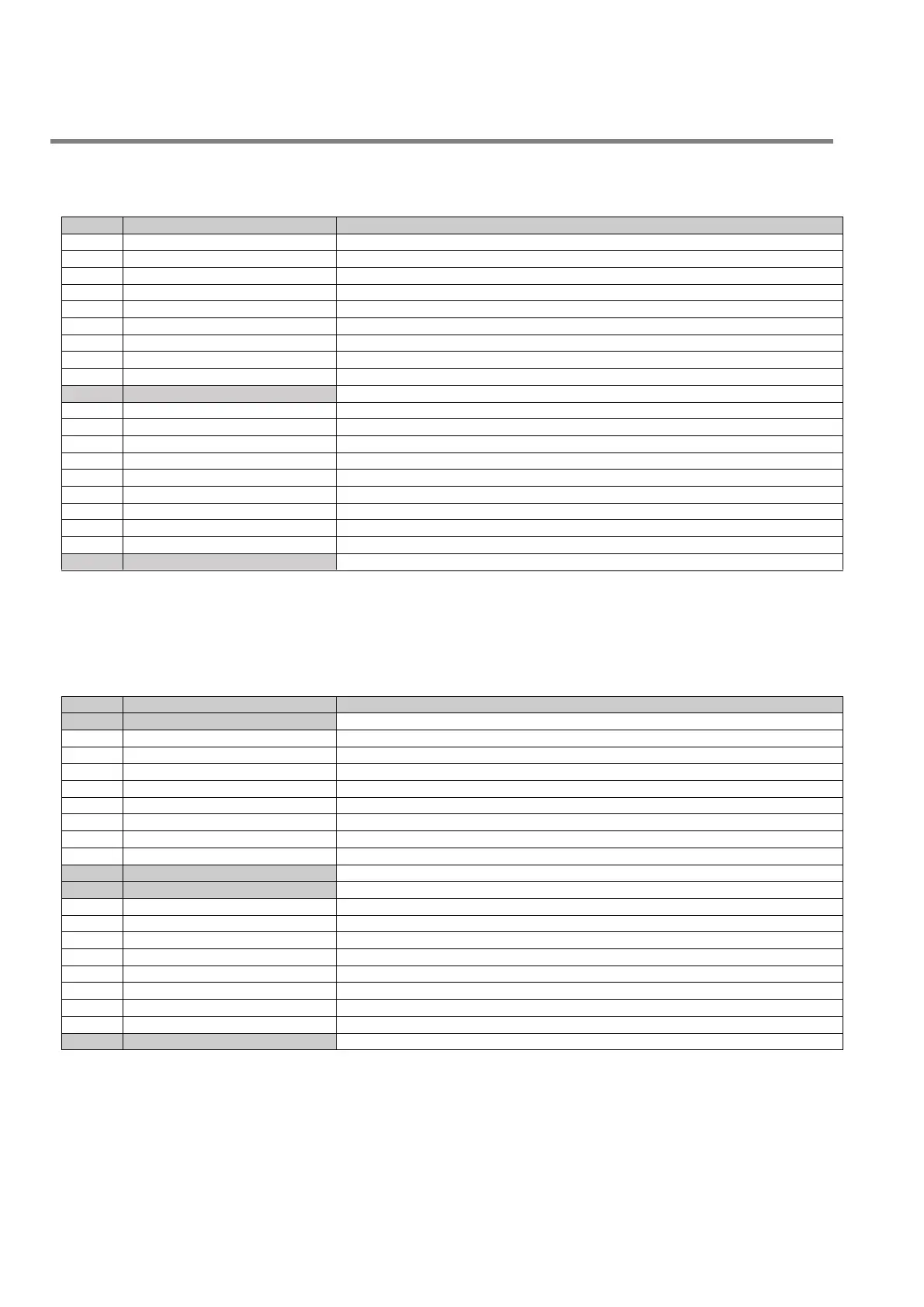
3.2 Digital Input (Card IMI220-6100A001).
Profile start signal for group 1 regulators
Photocell parison group 1
Measure signal of parison length for group 1 regulators
Signal for mould ready to collect group 1 parison
External enable for group 1 purge
Profile start signal for group 2 regulators
Photocell parison group 2
Measure signal of parison length for group 2 regulators
Signal for mould ready to collect group 2 parison
External enable of group 2 purge
Die gap closing signal during accumulation phases
Operation enable of regulators and extruders
Presence alarm in machine
Indication of machine alarm pieces
Indication of machine in automatic or manual mode
Decrease of produced pieces caused by a rejection
3.3 Digital Output (Card IMI220-6150A001).
Indication of reached accumulator end of filling quota
Indication of reached end of extrusion quota
Sync command n°1 of first thickness regulator
Sync command n°2 of first thickness regulator
Sync command n°3 of first thickness regulator
Sync command n°4 of first thickness regulator
Sync command n°5 of first thickness regulator
Command of serial marker actuator
Increase command for extruder 1
Decrease command for extruder 1
Increase command for extruder 2
Decrease command for extruder 2
Enable command from timer switch
Head number 1 in calibration mode
 Loading...