© MOOG 2019
This document is subject to MOOG INTELLECTUAL AND PROPRIETARY INFORMATION LEGEND . The details are on page II.
The extruder barrel and/or screw can be severely damaged if the die gap closes when the
extruder is running. A mechanical motion stop must be installed which will not allow the die gap
to close.
1-5-3. MOOG DIE GAP TOOLING ACTUATORS
The Die Gap Tooling Actuator is designed specifically to control the die gap motion in blow molding extru-
sion heads. Their design specification includes: Low friction, Long life piston and rod seals. Graphite flake
cast iron rod bearings to absorb potential side loads and high temperatures. Provision for blow air through
the piston rod, and pre adjusted position feedback transducer.
The mounting provisions for a die gap tooling actuator must include: a strong mounting structure, provi-
sions for axial and parallel alignment of the tooling actuation rod (mandrel) with the die gap actuators rod,
provisions to allow the actuator stroke center and the tooling’s effective stroke center to coincide, tooling
motion stops to protect the tooling and/or extruder. Figure 1-6 illustrates a packaged tooling actuator.
Core control Actuator (example: J085-139)
The actuator rod extends when the cur-
rents of the servo valve pins A, C are pos-
itive with respect to the currents of the pins
B, D
Pin A
Pin B
Pin C
Pin D
Pin E
Pin C becomes positive with respect to pin D
when retracting the actuator
Connector compatible with
MS3106-14S-5S
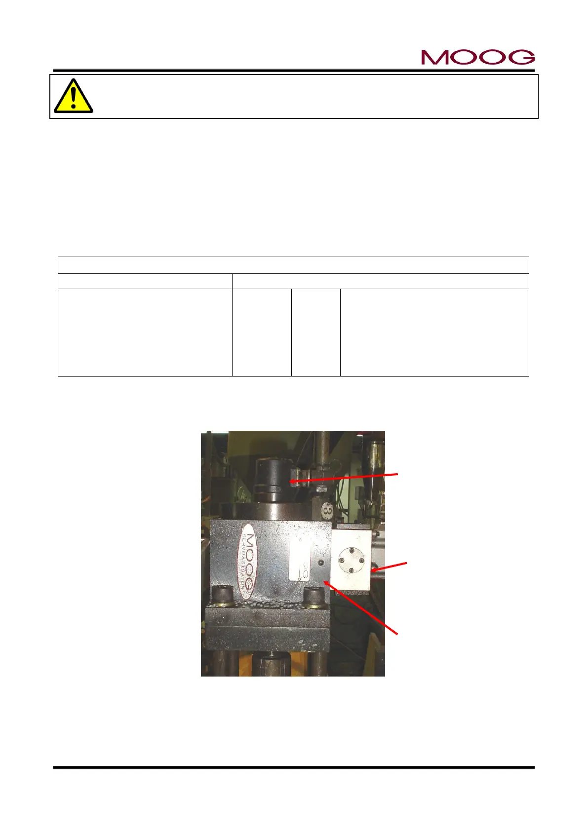
1-5-4. CYLINDER INSTALLATION
Figure 1-9 shows an installation example of Moog's die gap core control actuator.
Figure 1-9 Typical Cylinder Installation
DCDT Toolong Posi-
tion Transducer

 Loading...